The most import thing for being able to generate proper animations in multiple
colours is that it is possible to control every single colour of the 1024 LEDs
separately. This means that it is possible to turn on red and green (=yellow) on one
RGB LED while on another LED only blue is turned onfor example.
To achieve this, a lot of LED drivers, which basically are shift registers with some
additional control logic so that only one resistor is needed to adjust the current for
all LEDs on one driver, are needed.
All 32 layers with the LEDs on them are rotated around a common axis with 20rps.
The necessary brushless DC motor has got an internal control logic built into it and
can be controlled over a couple of simple digital inputs whose function can be preprogrammed.
One full rotation is separated into 1024 individual"refreshes" for all LEDs, where
they are able to change their colours, so that 3D pictures or animations can be
displayed. The refreshes occur when an optical forksensor passes by a tooth of a
fix mounted crone, which has one tooth for each refresh. When a refresh occurs all
LED drivers are filled with new pre calculated dataand once the shift registers are
full the data is shifted out to the LEDs. Knowing which animation is supposed to be
displayed, the data can be calculated and stored onan external flash memory
before displaying it earlier.
Because of the huge amount of data and LEDs a single microcontroller would not
be fast enough to put out the new data for every refresh in time. Besides too many
microcontroller pins would be needed to connect allof the electrical components.
For this reason every single layer has its own microcontroller and its own flash
memory. This way the data can be loaded from the flash and put into the LED
drivers 32 times faster than with just one microcontroller and also the number of
pins needed are no problem anymore. The practical thing about this solution is
that the hardware layout design and the firmware are the same for all of the 32
layers.
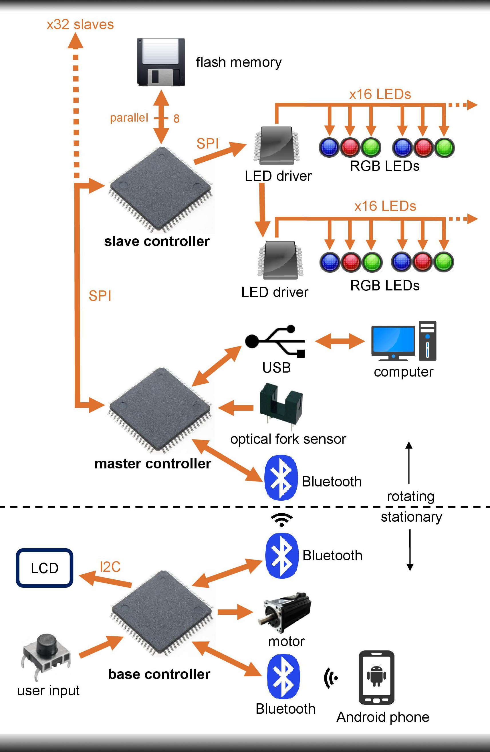
To save all the animation data in the different flash memories an additional
microcontroller, which is the master of all the other (slave) microcontrollers on the
layers, is needed. The master is connected to the slaves per an modified SPI bus
with two additional bus wires. The addresses of theindividual layers are the only
things which alter from layer to layer. However this is necessary so that the master
controller is able to select each layer for data transfer individually. To make it
possible to use the same hardware and firmware for all layers the same 5 I/O pins
of the slave controllers are used to set the address. All of them are pulled to
ground by default after production. The only thing that needs to be done to set the
addresses is to connect the traces between the individual I/0 pins and V+
differently for each layer (5 traces -> 32 possibilities). The firmware scans if the I/O
pins are connected to V+ or not and sets a bit maskwhich represents the address
according to the connections then.
All of the animation data has to be sent to the master controller before it can be
passed along to the slaves with the SPI bus. The data transmission between a PC,
which already stores all of the necessary data, andthe master controller is
achieved per USB.
Actually one more additional microcontroller is needed because the motor doesn't
rotate along with the LEDs. The motor is wired to the so called "base board", which
is the only board which doesn't rotate, along with an LC display which is needed
for control purposes. The LCD offers an easy to operate 4 button GUI where the
different animations can be selected, paused and rotated and brightness can be
adjusted. The data between the master controller (main board) and the base
controller can't be transmitted per wires because the base board is fixed and the
main board rotates. To make a communication betweenthese two possible one
Bluetooth module is needed on each board. Because one module can only have a
connection at a time and it should always be possible to control voLumen with a
PC or an android phone in addition to the LCD another Bluetooth module is placed
on the base board.
The energy transmission to all of the electrical components which rotate is done by
simple slip rings, as they are very reliable and easy to use. The general power
source is the main's electricity which powers threepower supplies, one for the
electronics, one for the LEDs and one for the motor .
The animation data has to go quite a long way before it can be displayed on
voLumen. At first an animation has to be modelled in a 3D rendering program like
Cinema4D (In the end the user will see the exact same animation which he can
see on the 2D screen of the computer, after he has finished modelling, in real 3D
on voLumen!). The next step is to render the animation with picture files as output,
one picture for each frame (equal to one rotation) on voLumen. This means that 20
* 60 pictures are needed for one minute of animation playback, assuming
voLumen is really spinning at exactly 20rps.
After rendering, a circular ring is virtually put over these pictures by software. This
circular ring is not a completely filled space, it consists of single pixels where each
pixel represents exactly one voxel on voLumen. Thismeans that the radius of the
circular ring consists of 32 such pixels, one for each LED, and the whole ring
consists of 1024 of these 32 pixel lines, one representing one refresh. To achieve
a proper circular ring you can't put those pixels directly next to each other because
the natural alignment of the pixels on any 2D display is a square and not a circle.
For this reason, there are always some "empty pixels" in between of the pixels
which represent the voxels, to draw a proper circular ring.
Next the software goes through all of the circular ring's pixels which represent a
voxel (scanned pixels) and checks the colour of therendered frame's pixels which
lie directly underneath the circular ring's pixels.Depending on the colour that lies
underneath, the according bits for the LEDs, which generate the voxels, are set. If
the colour under one such scanned pixel is cyan (green + blue) for example, the R
LED value is set to 0 and the G LED and B LED values are set to 1 for the specific
LED and refresh step which has been scanned. Once all the animation data has
been calculated with this method the data is sortedby software so that voLumen
only needs to shift out the data into the LED drivers, without needing to worry
about the proper order of it. After sorting the data, each frame's data is saved in its
own binary (.bin) file.
At last, the data from the binary files is read again when the computer sends the
data to the voLumen master controller per USB. The master controller then sends
the right data to every layer per SPI bus. Finally each layer stores the received
data on its own flash memory.
Discussions
Become a Hackaday.io Member
Create an account to leave a comment. Already have an account? Log In.