 Andrew Mitz
The writing between the Raspberry Pi and the front panel PC board is slightly different among the Raspberry Pi 3B, Raspberry Pi 3B+ and Raspberry Pi 4. I use a Raspberry Pi 3B+. The 3B and 3B+ run cool, which provides many hours of service. The Pi 4 is much warmer. I would rather not run it without a small fan. Fans tend to fail over time, so the 3B or 3B+ seems like a better choice. I buy the 3B+ because it is a newer design, but the 3B works file.
To make the wiring differences more clear, I have updated the schematic with notes on each Raspberry Pi. I
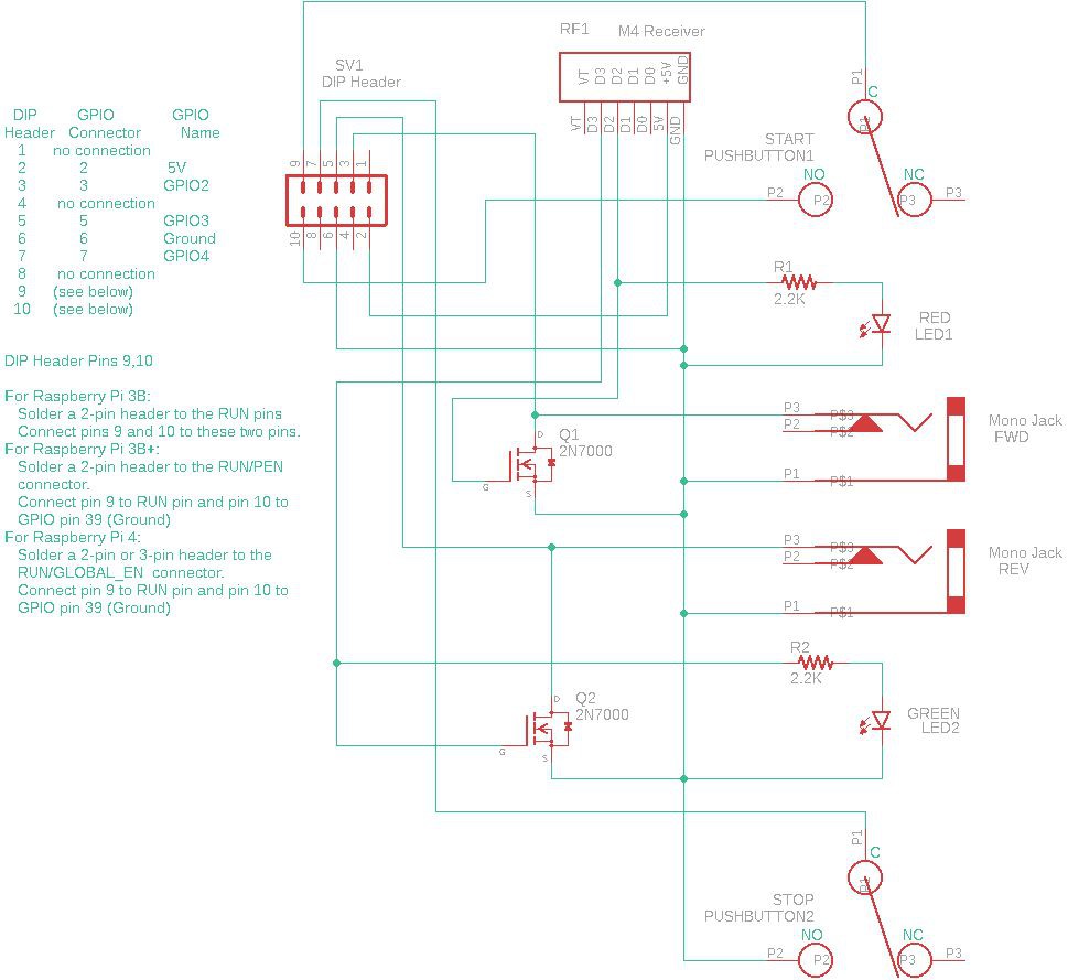
To make a simple harness I like to use a 10-pin female header to plug into the front panel board. I use an 8-pin female header on the GPIO header of the Raspberry Pi. I solder color-coded ribbon wires between the two using standard color codes. The pin mapping from the front panel board to the GPIO pins are 1:1 for these pin numbers: 2, 3, 5, 6, 7. The last two pins of the 10-pin header connect depending on the specific Raspberry Pi board.
For the Pi 3B, simply wire pins 9 and 10 to the two RUN pins. Note, on all the Raspberry Pis, you must install a male header on the RUN pins yourself. I find this a big annoyance.
For the Pi 3B+ or the Pi 4, connect pin 9 to the RUN pin. Connect pin 10 to GPIO 39, which is a ground. The RUN header is 2 pin on the Pi 3B+. On the Pi 4, the header has three contacts and is called RUN/GLOBAL_EN. It still has a RUN pin.
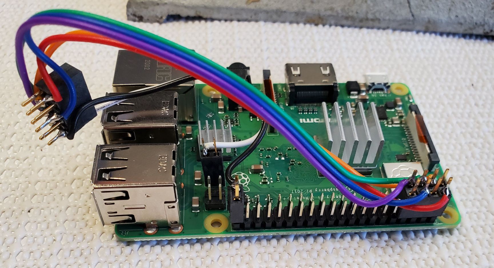
This picture shows the wiring of the cable harness before assembly. The example is a Pi 3B+.
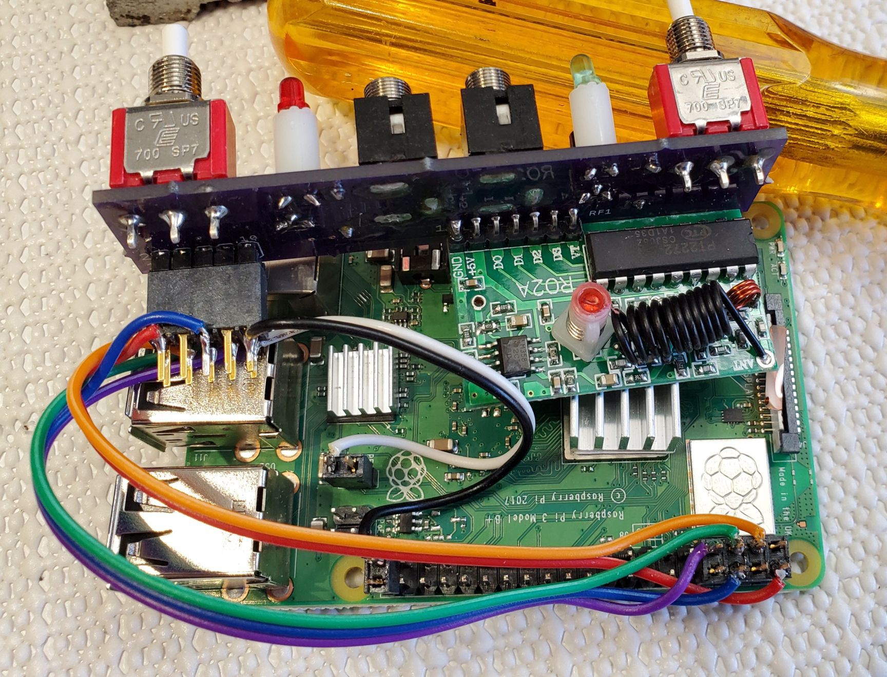
The next picture shows the harness wiring attached to the front panel PC board.
Discussions
Become a Hackaday.io Member
Create an account to leave a comment. Already have an account? Log In.