Overview
The 8-bit microcomputers of the 1970s and 1980s frequently used audio cassette tapes for data and code storage and, with the recent resurgence of interest in vintage computing, there is a need to be able to read and write these tapes without needing vintage hardware that may be unavailable or unreliable. To address this, I'm designing a vintage cassette I/O board for the popular RC2014 computer bus.
Vintage cassette I/O boards were generally implemented with a combination of discrete components and TTL logic. Each format required a different circuit. It's impractical to support all of these circuits on a single board, so I'm going to design this board with a minimum of external circuitry and leave the heavy lifting of encoding and decoding the signals to DSP code running on a simple 8-bit micro controller, the Atmega 1284.
I've never designed a PCB all the way from schematic to finished product, so this project is a good opportunity to do so. In recent years, it has become very practical and economical to produce short runs of boards. I'm going to use a popular, open-source tool, KiCad, for the schematic design and PCB layout.
Formats
Kansas City Standard
The Kansas City (or Byte) Standard (KCS) is a way of storing digital data on standard Compact Audio Cassettes at data rates of 300 to 2400 bits per second (at 300–2400 baud) that was first defined in 1976. It originated in a symposium sponsored by Byte magazine in November 1975 in Kansas City, Missouri to develop a standard for storage of digital microcomputer data on inexpensive consumer quality cassettes. Although the KCS standard existed from the earliest days of the microcomputer revolution, it failed to prevent a proliferation of alternative encodings. Most home computers of the era used their own formats that were incompatible with KCS or each other.
See Kansas City Standard for more information.
MITS Altair Cassette Interface
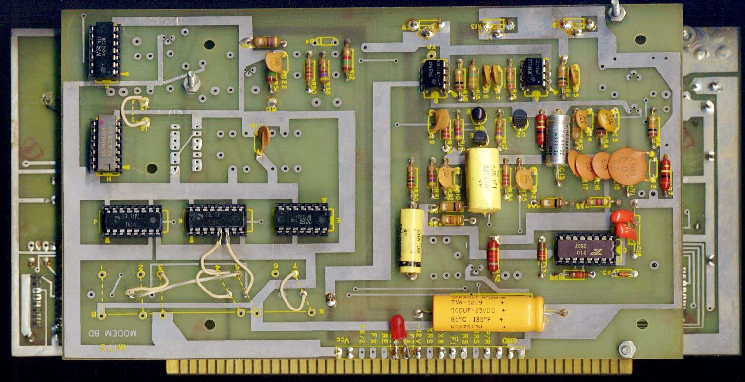
The MITS Altair cassette interface was provided by a daughter card (the 88-ACR) attached to a serial I/O card (the 88-SIO). It operated at 300 baud and used a frequency-shift-keying (FSK) modulation scheme based on high/low frequencies of 2400/1850 Hz. It was also notoriously unreliable and required frequent calibration.
See MITS Altair 88-ACR Manual.
See Altair 8800 for more information.
Tarbell Cassette Interface
The Tarbell cassette interface was an expansion card, designed by Don Tarbell in 1976, for the Altair 8800 and other systems based on the S-100 bus. It supported the 1975 Kansas City Standard (300-2400 baud) but also introduced a much faster Tarbell standard which became a de facto standard.
See Tarbell Cassette Interface Manual.
See Tarbell Cassette Interface for more information.
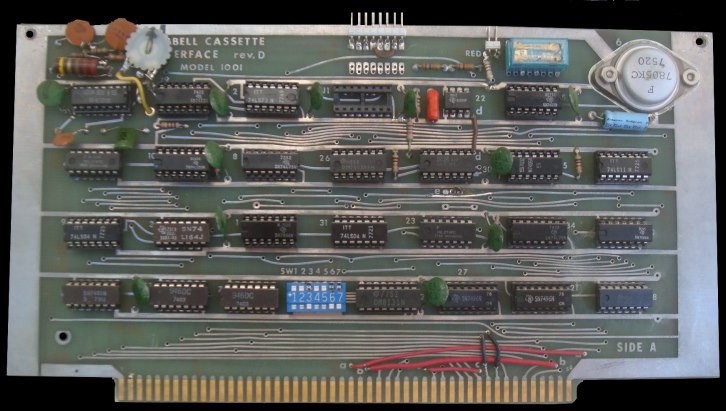
Computer Users' Tape Standard (CUTS)
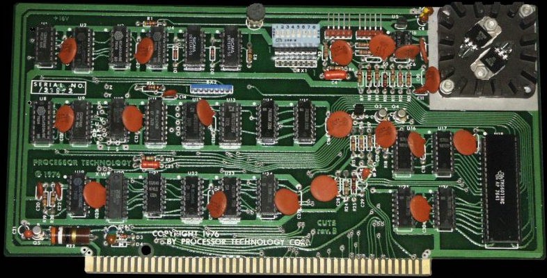
The CUTS Tape I/O interface was introduced in 1977 by Processor Technology for its SOL-20 computer. It supported the 1975 Kansas City Standard (300-2400 baud) but also introduced a new format, CUTS, which supports 300 and 1200 baud.
See Processor Technology CUTS Manual.
See CUTS Tape I/O for more information.
Hardware
Microcontroller
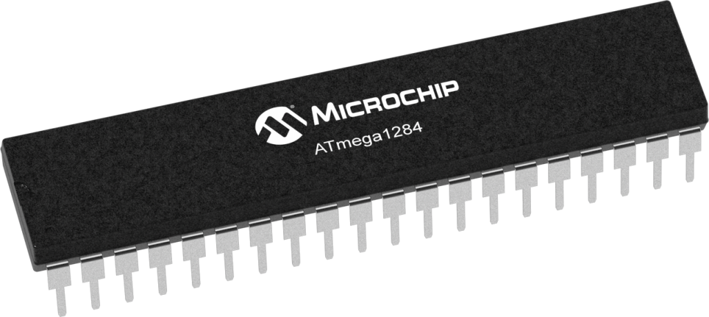
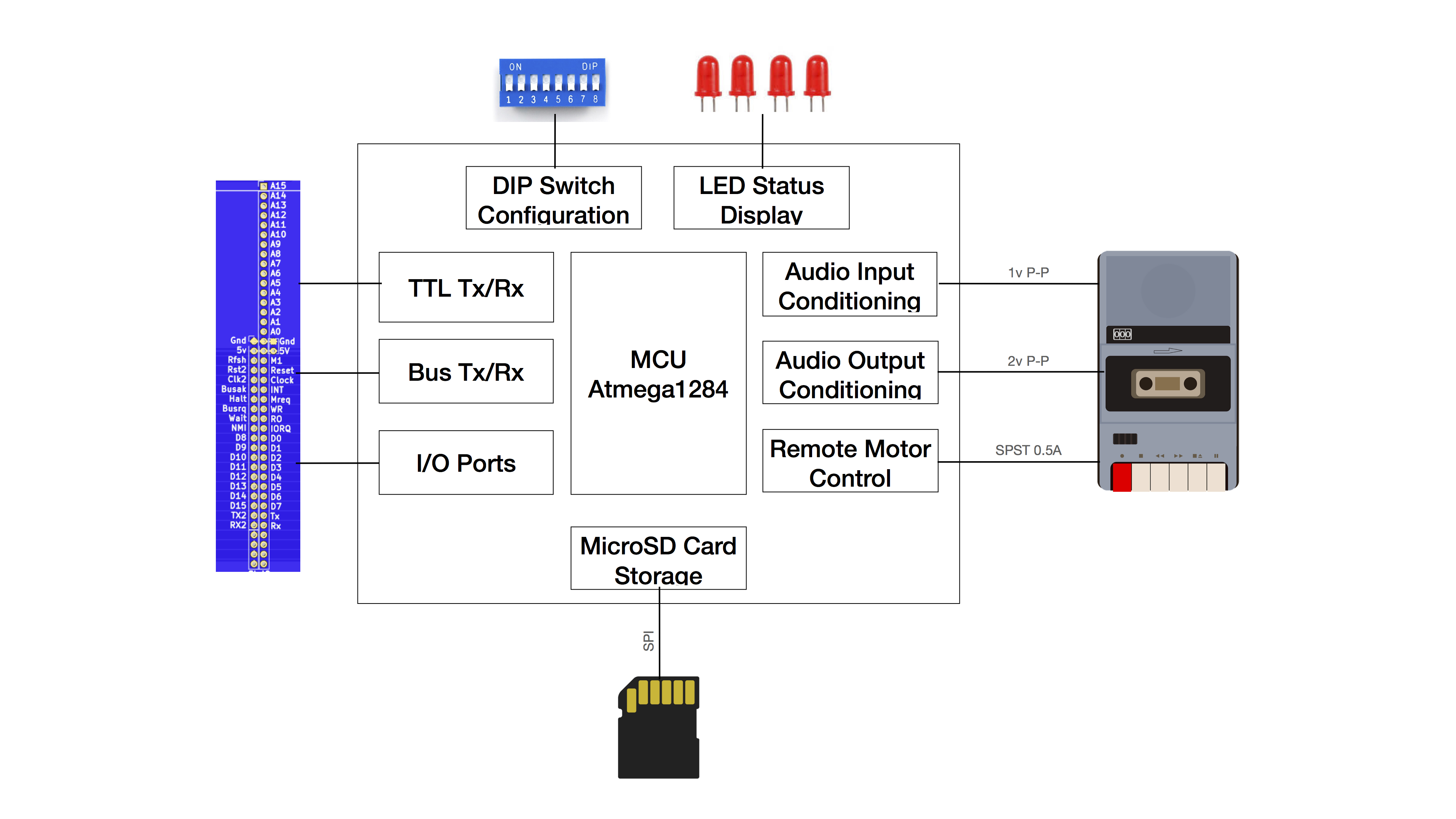
The micro controller I've chosen for this project is the Atmega1284. It's inexpensive, readily available, compatible with Arduino, and has sufficient pins, memory, peripherals, and horsepower. It's also available in a through-hole DIP package.
See Atmega1284 for more information.
Virtual I/O
The virtual I/O hardware uses a configurable address decoder to determine when data needs to be read or written from the cassette device. It triggers a micro controller interrupt to service the request and read or write a data stream that can be encoded into or decoded from WAV format by the audio I/O software. It can also be read from or written to a microSD card.
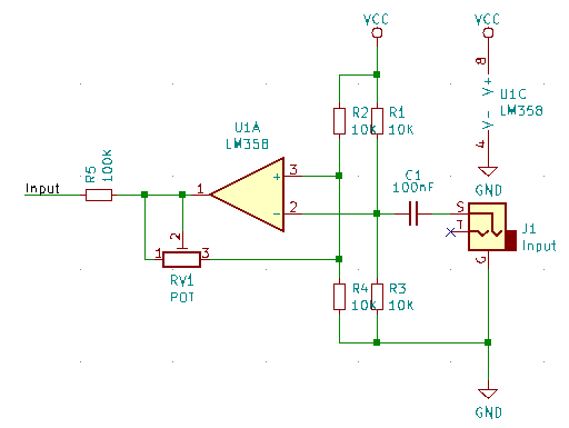
Audio I/O
The audio I/O hardware is divided into three subsystems: input, output, and remote.
The audio input hardware is used to condition the analog cassette audio output (typically +-2V p-p) to the analog input (0-5V) of the micro controller (0-5V). It also provides some circuit protection and noise filtering.
The audio output hardware is used to condition the digital PWM output of the micro controller (0-5V) to the analog cassette audio input (typically +-1V p-p). It also provides some circuit protection and noise filtering.
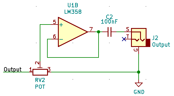
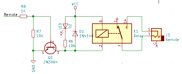
The audio remote hardware is used to control a relay that is typically used to turn the cassette deck motor on or off. The use of a relay isolates the board from the cassette deck circuitry.
MicroSD Drive
The microSD drive I've chosen is the Pololu breakout board. It's cheap and it works well. It's also already assembled, so it will make building the board easier.

See SD Card Breakout for more information.
Software
Interface
The primary interface for the board is a command line interface running over the built-in serial port.
Virtual I/O
The virtual I/O software emulates a serial I/O port and interfaces directly with the RC2014 bus to read or write a data stream that can be encoded into or decoded from WAV format by the audio I/O software. It can also be read from or written to a microSD card.
Audio I/O
The audio I/O software is divided into three subsystems: input, output, and remote.
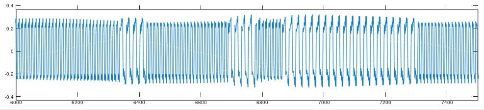
The audio input software converts analog ADC input into digital input and standard WAV format data that is analyzed using simple digital signal processing (DSP) techniques, typically using a Goertzel filter, and converted into a data stream.
The audio output software converts a data stream into standard WAV format data and digital PWM output that is converted by the output hardware into analog audio output.
See Goertzel Algorithm for more information.
MicroSD Drive
The micro SD drive software uses the open-source FatFS library is used to provide a standard FAT32 file system that can be used to exchange data with a personal computer.
See FatFS for more information.