 kutluhan_aktar
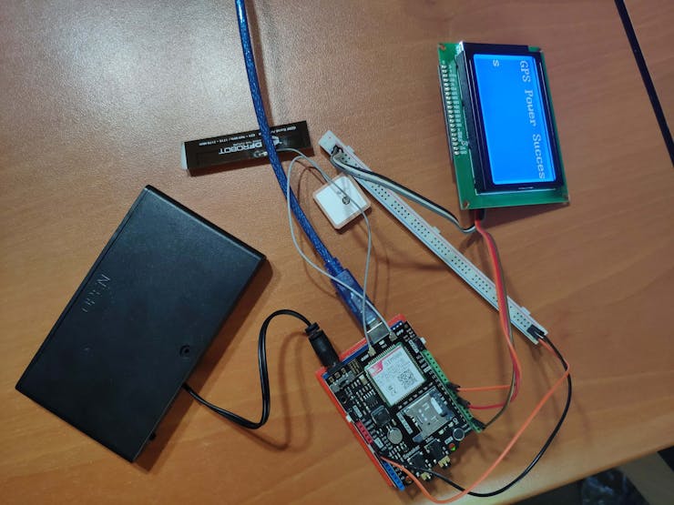
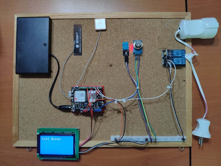
Also, gas leakage, instigated by pipe expansion, is a dangerous problem while temperature is rising. Therefore, I added an MQ-135 Gas Sensor to the device, which detects NH3, NOx, Alcohol, Benzene, Smoke, CO2, to check the hazardous gas status in my room. And, most importantly, to be able to send commands to control the cooling fan via SMS messages and get the weather and gas information as feedback, I used a SIM808 GPS/GPRS/GSM Shield sponsored by DFRobot.
Sponsored products by DFRobot:
- SIM808 GPS/GPRS/GSM Shield For Arduino | Inspect
Step 1: Programming Arduino Uno
Download the required libraries:
For SIM808 GPS/GPRS/GSM Shield | Download
For 3-wire Serial LCD Module | Download
For DHT11 Temperature and Humidity Sensor | Download
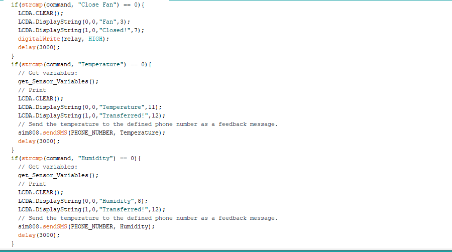
Do not forget that the SIM808 receives SMS messages as char arrays instead of strings. So, you have to use the strcmp function to make comparisons to detect the requested command.
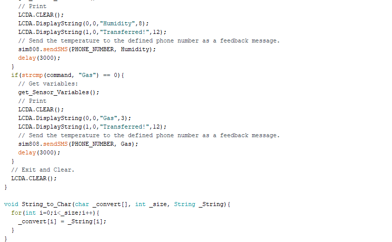
And, the 3-Wire Serial LCD module prints only char arrays. After creating a data string, use the String_to_Char function to convert strings to char arrays.
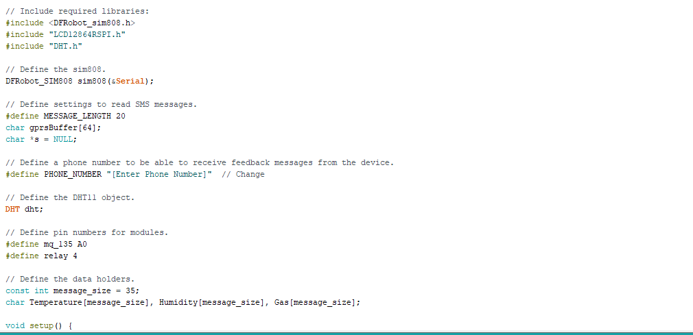
- Include required libraries.
- Define the sim808 object.
- Define required settings to read SMS messages.
- Define a phone number to be able to receive feedback messages from the device.
- Define the DHT11 object.
- Define pin numbers for modules.
- Define the data holders.
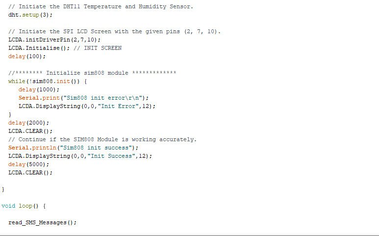
- Initiate the DHT11 Temperature and Humidity Sensor.
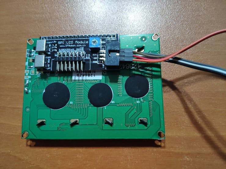
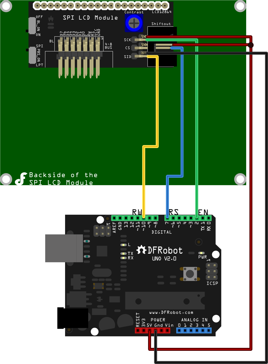
- Initiate the SPI LCD Screen with the given pins (2, 7, 10).
- Initialize the sim808 module.
- Continue if the SIM808 Module is working accurately.
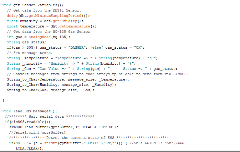
- In the get_Sensor_Variables() function:
- Get data from the DHT11 Sensor.
- Get data from the MQ-135 Gas Sensor.
- Detect the gas status depending on the value generated by the MQ-135 - OK or DANGER.
- Convert messages from strings to char arrays to be able to send them via the SIM808.
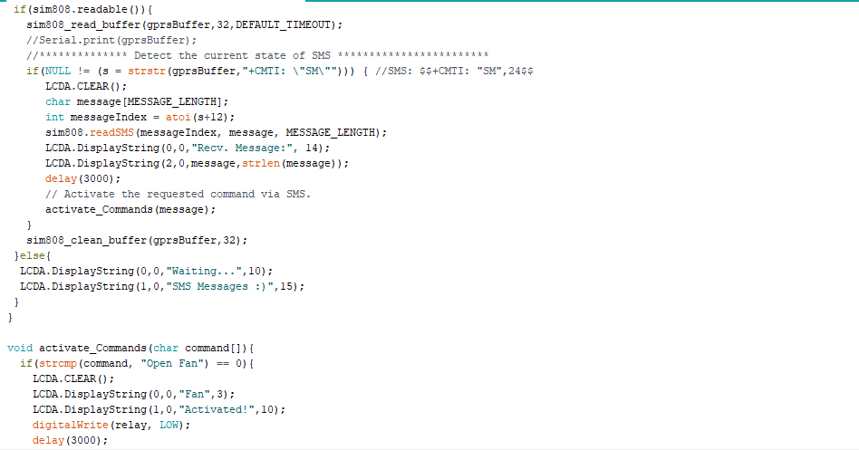
- In the read_SMS_Messages() function:
- Wait for serial data from the SIM808.
- Detect the current state of SMS.
- Print the received SMS message.
- Activate the requested command depending on the SMS message.
- In the activate_Commands function:
- Using the strcmp function, detect the requested command by the user to execute features related to that command.
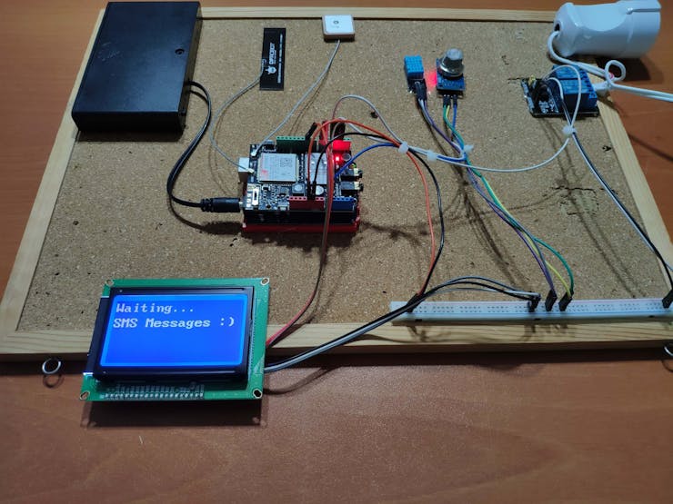
Connections and Adjustments
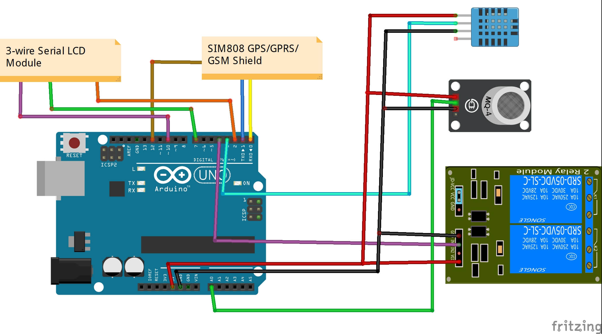
// Connections
// Arduino Uno:           //                               SIM808 GPS/GPRS/GSM Shield For Arduino
// D0 --------------------------- RX
// D1 --------------------------- TX
// D12 -------------------------- POWER
//                               3-wire Serial LCD Module
// D2 --------------------------- SCK
// D7 --------------------------- CS
// D10 -------------------------- SID
// 5V --------------------------- VCC
// GND -------------------------- GND
//                               DHT1l Temperature and Humidity Sensor
// D3 --------------------------- S
//                               MQ-135 Gas Sensor
// A0 --------------------------- A0
//                               2-Way Relay Module
// D4 --------------------------- IN1

Note: D0, D1, D12 pins are occupied by the SIM808 GPS/GPRS/GSM Shield.
Connect an external battery (7-23V) for the SIM808 module to work properly.
Attach the GPS antenna and the GSM antenna to the SIM808 shield.
Insert a SIM card into the SIM slot on the SIM808 shield.
Before uploading the code, set the function switch on the shield to None (1).
Upload the code.
Then, set the function switch to Arduino (3).
Press the Boot button on the shield until seeing the Net indicator LED flashing every 1 second and wait for the SIM card to register the network - the Net indicator LED will slowly flash every 3 seconds.
Click here to get more information about the SIM808 GSM/GPS/GPRS Shield.

Connect the 3-wire Serial LCD Module to the Arduino Uno.
To switch to the 3-Wire mode, set the PSB_ON switch to SPI.
Click here to get more information about the 3-wire Serial LCD Module.
Connect the DHT11 Temperature and Humidity Sensor, the MQ-135 Gas Sensor, and the 2-Way relay to the Arduino Uno.
Attach a plug to the 2-Way relay to be able to control the cooling fan easily.
After...
Read more »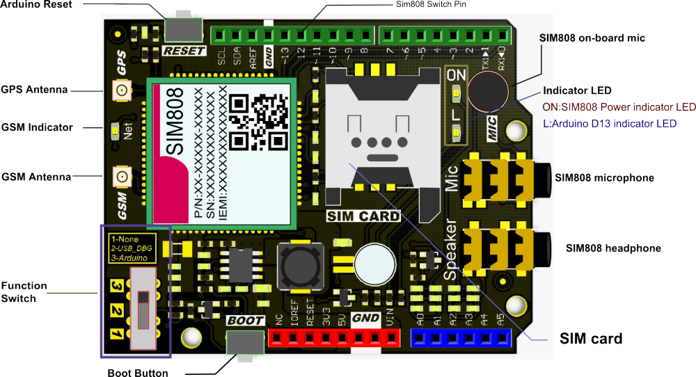


 clewsy
Please feel free to leave a comment here if you have any questions or concerns regarding this project :)