 Bob Alkire
So I went to Amazon to look for disinfecting chambers and what they had for looked sketchy. I asked my friend Keith Hargrove to take a look too. Neither of us could find much that we could trust to do a good job. We talked about building our own. We found a few DIY projects but they looked like a recipe for trouble. A UVC lamp that is capable of destroying the virus poses a health risk if you are exposed to it. Keith came up with a great idea of retrofitting a Microwave. The Microwave has a radiation sealed chamber, switched interlocking door, safe area for AC power, timer, light, a little turntable and power cord.
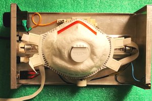
I used a UVC germicidal tube designed for this kind of application and it has a long track record. It is in a small enclosure so it is within close proximity of the UVC tube and we made an instrument that would measure the intensity.
When you are re-purposing appliances for what they weren’t intended for, there are unforeseen circumstance.
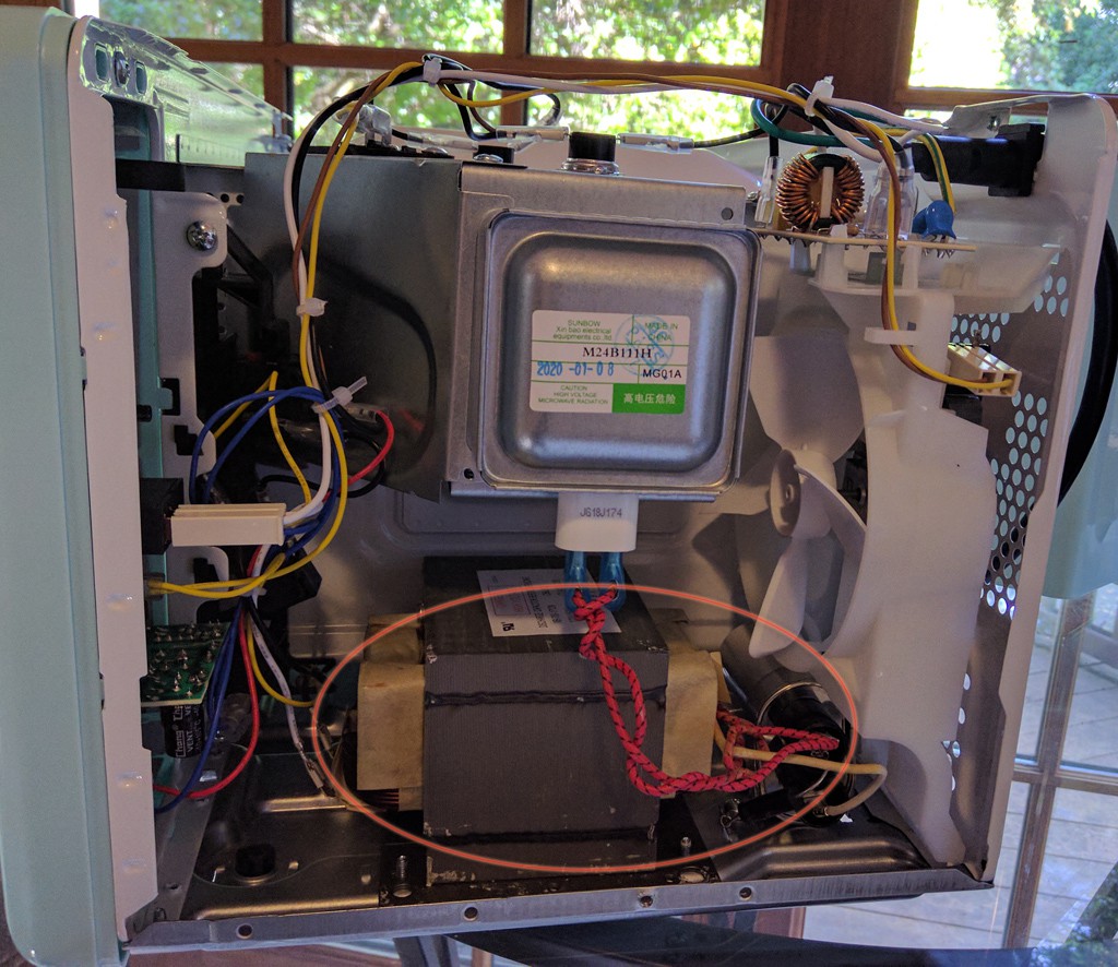
For example, it would be convenient to use the power to the magnetron transformer – it has a beefy relay and is switched on when the door is closed and on a timer. The problem is microwave power is controlled by cycling this relay using a long duty cycle. That is if the power level is set 50% it may cycle power every 10 seconds. I found that, independent of power level, it would do an 80% on 20% off duty cycle after 8 minutes, probably to keep the magnetron and electronic from overheating. This kind of duty cycle will shorten the life of the UV bulb. The alternative is to use the relay that controls, the turntable and fan. This relay stays on while the magnetron power cycles but the interlocks and timer still controls them.
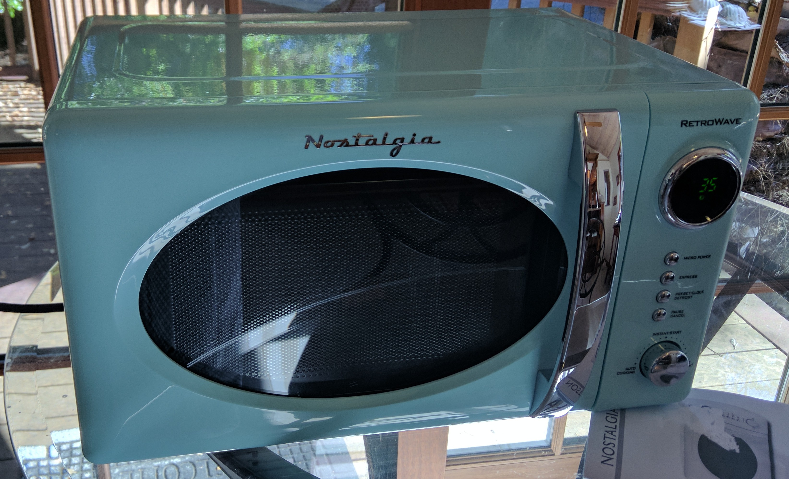
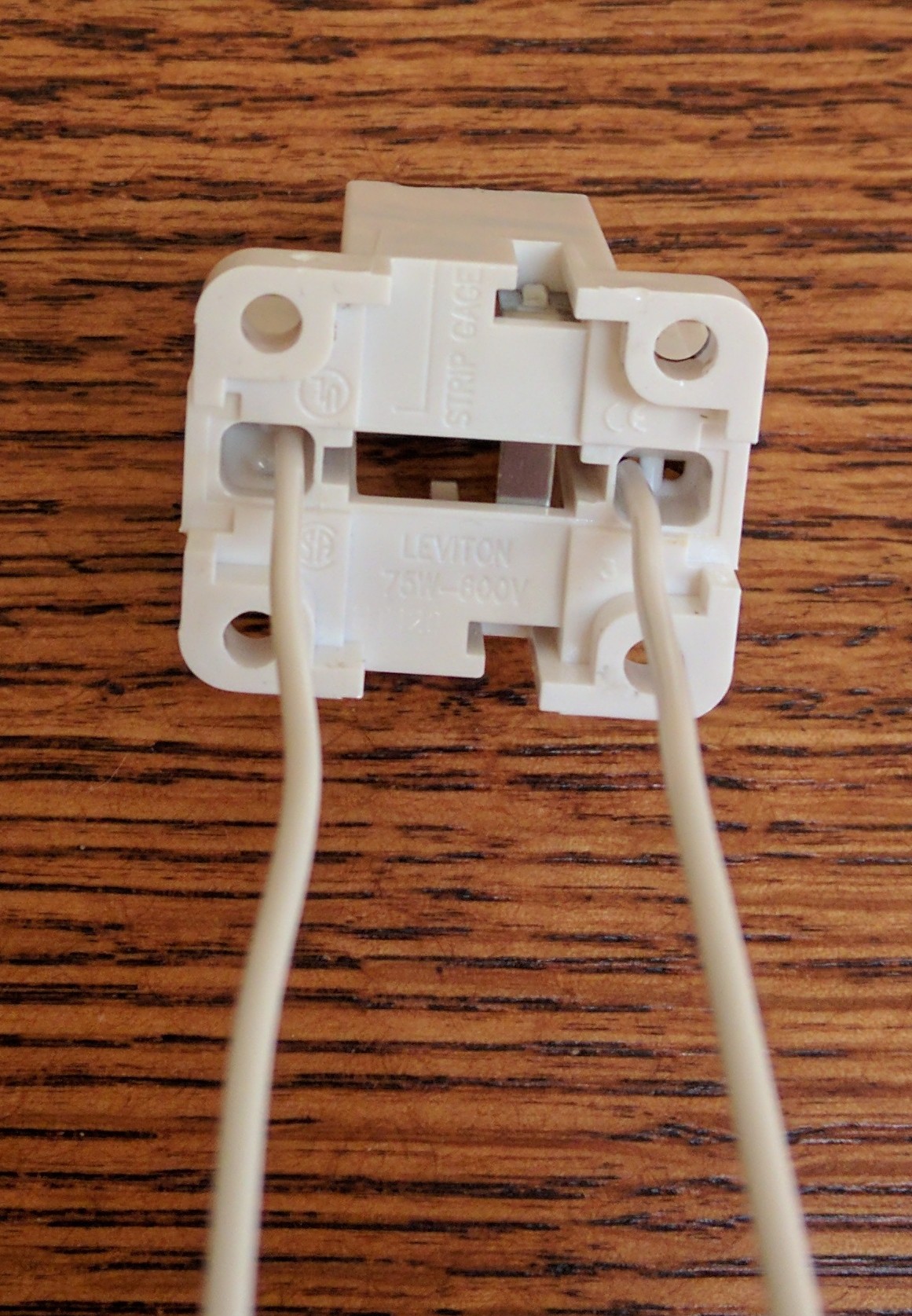
I went with a 6in 9W compact fluorescent UVC disinfectant tube, GCF9DS. This is a folded tube that mates with the G23 two prong socket. This is old school fluorescent with integrated starter and a 9W magnetic ballast. Definitely not recommended for new designs but all the parts are still available. Since it has an integrated starter, you cannot use solid state or “electronic” ballast for these tubes and it will flicker when it starts up. You could probably scrounge a microwave although a simple new one can be gotten fairly cheap. Advantage of a new one is it won’t smell like old food. (the ozone generated from the UV tube may kill the smell). I got a cheap retro-looking microwave, the “RetroWave Nostalgia”. The chamber length is 11 inches and the tube will fit.


 Giovanni Carrera
 Keith
Keith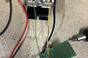
 Will Stone
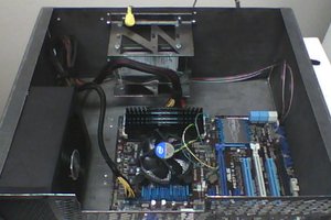
 Jake
Jake
I whipped together a little UV-C diode based sterilization board and in what I've researched, yeah, getting a UVC excimer lamp outside of government surplus is gonna be a toughie. getting the power and wavelength isn't gonna be easy. However, keep in mind that you simply need to excite a sufficient amount of matter. 10W UV-B COB modules with aluminum backings can be gotten on eBay for cheap. No need to follow the exact CDC dosing of UVC. Blast the biches with enough watts of UV and those suckers bound to die.