 Aleksey
“ROTOR”- Hydraulic Motor Project.
The "Rotor" project is under development. The theoretical part gave great hope for the production of a hydraulic engine with a superior, all analogues, efficiency of 75%. To test the theory we need:
- make a prototype,
- create a hydraulic system
- check the efficiency.
A hydraulic motor is a mechanical actuator that converts hydraulic pressure and flow into torque and angular displacement (rotation).
Hydraulic motors have many applications in:
- Agricultural Machinery;
- Road Work Machinery;
- Construction Work Machinery;
- Military Vehicles
This motor is utilized when it is not possible to transmit torque by means of a rigid coupling (shaft, chain, gear, etc).
The efficiency of the "ROTOR" is much greater (75%) when compared to hydraulic motors such as: Axil plunger motors, Gear motor, Gerotor motors, Radial piston motors.
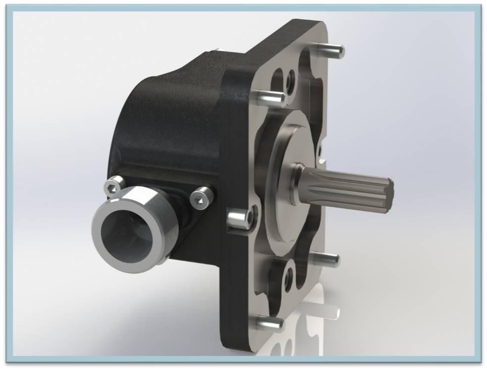
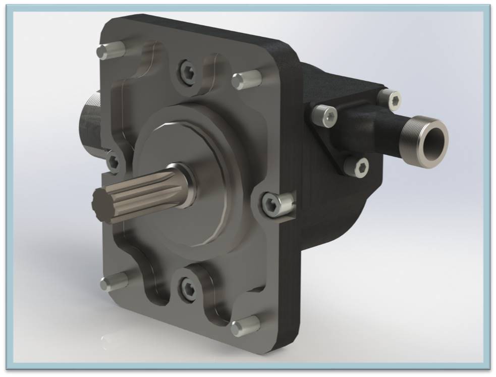
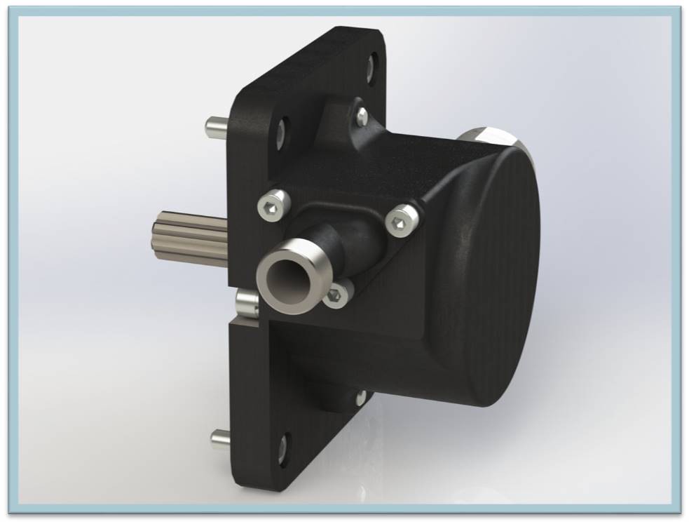
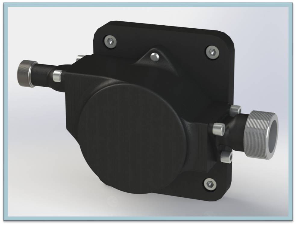
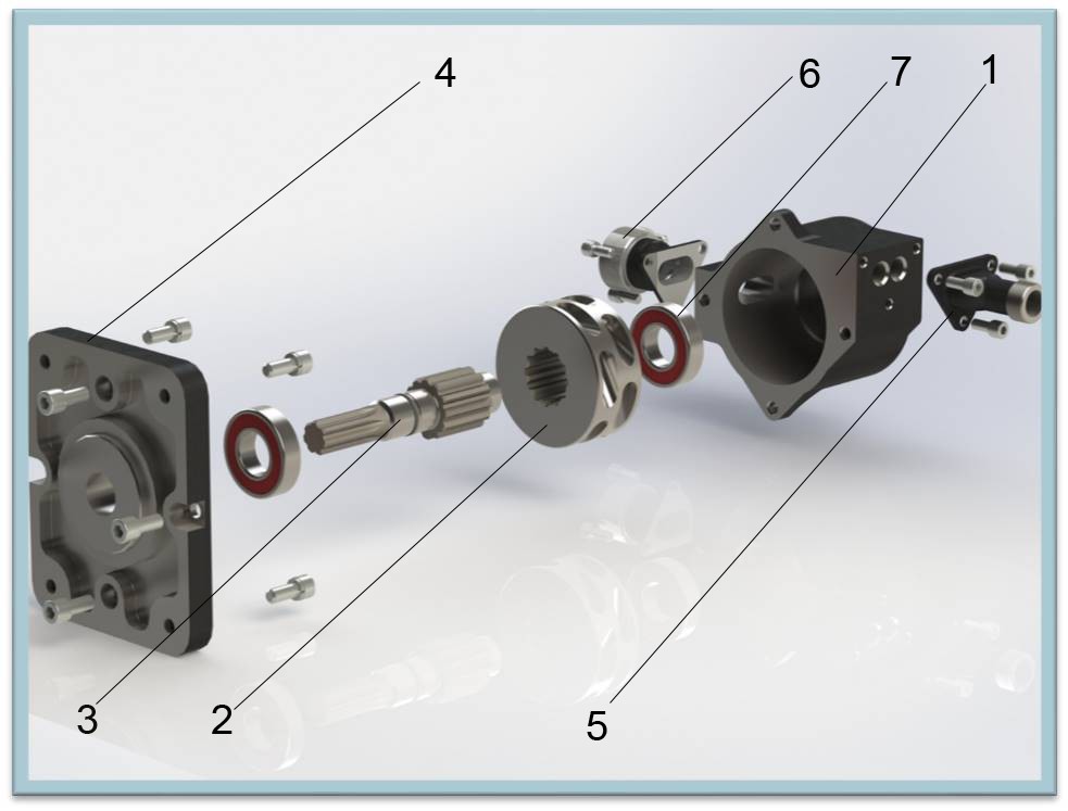
The composition of the hydraulic motor “ROTOR” :
1 Body – а cast machined part;
2 Rim - molded machined part;
3 Shaft - part made form a variety of mechanically processed materials;
4 Cover - part made form a variety of mechanically processed materials;
5 Inlet pipe - cast machined part;
6 Outlet pipe - cast machined part;
7 Bearing - standard piece.
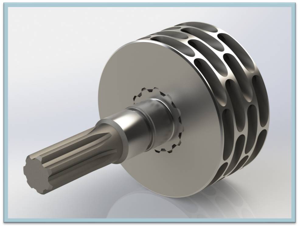
The rim and shaft make up the Rotor part, which is the main piece. Engagement between parts is provided with
evolving (rotating) teeth. When manufactured, the rim is casted, followed by machining.
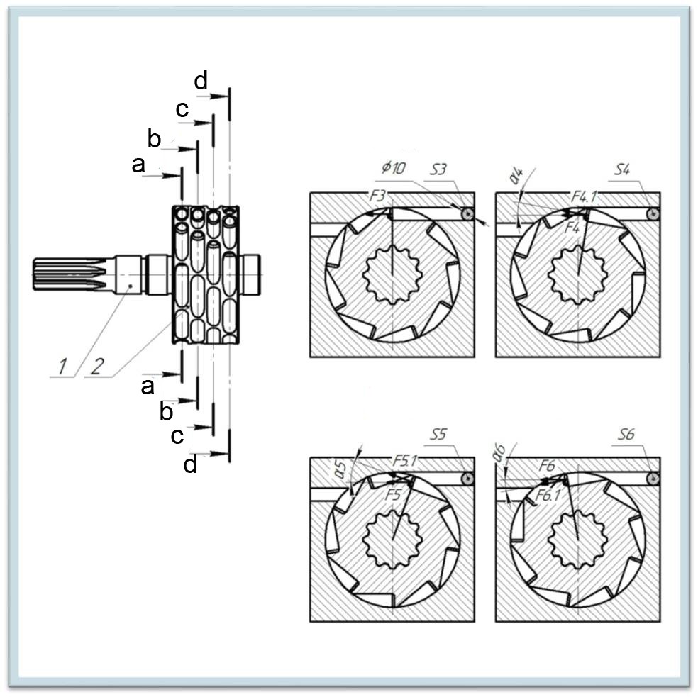
Analytical:
The key feature of the design is recesses in the form of truncated cone with an angle, made in the part rim. The recesses will provide directed flow of liquid and the efficiency will be at 76% minimum. The value is calculated and analytically obtained, while considering one recess from each row, they are indicated by the letters a, b, c, d. Distribution of the recesses along the axis of rotation into four rows and displacement of each row relative to each other by angle β will ensure smooth occurrence of torque.
The rotary engine performs two main tasks. 1 Increased efficiency compared to similar engines. 2 Expansion of hydraulic drives market. The design is as simple as possible and has a minimum of parts, which reduces the frequency of maintenance. The minimum number of parts reduces the cost and, accordingly, the market value. With all this, it has a high efficiency.
The design solution consists in the following, in the rotor there are recesses in the form of a truncated cone, which are distributed along the rotor circumference by an equal angle and distributed along the rotation axis in 4 rows, at the same time the rows are shifted relative to each other by an equal angle.
Truncated cone recesses will provide minimal fluid losses at the moment of passage through the hydraulic motor working cavity and thereby provide minimal power losses.
The distribution around the grooves and along the axis of rotation of the rows of grooves, as well as the displacement relative to each other, will ensure smooth operation.
The cone is the geometric figure that will provide the maximum rotor resistance, the greater the rotor resistance the higher the efficiency.
Increasing the efficiency of the hydraulic motor contributes to:
- reduction of weight and size characteristics of the energy source;
- reduction of meaningless fuel consumption;
- reducing exhaust emissions into the environment.
This project is patented and remains intellectual property.
Тhank you for your attention!

 Sean S Con
 Anteneh Gashaw
 Ali
Ali