Close
0%
0%

Bite-Sized Breadboards: Light Sensor

A short and fun interactive breadboard project. Cover the light sensor and the LED "eyes" light up!

Public Chat
Similar projects worth following
This is a beginning electronics project, great for putting together your first circuit! It uses a solderless breadboard, and after kitted up, no soldering or special tools are necessary for your students. We're working on a fully no-soldering-needed kit.

We like interactive projects, we think it' s just more fun to put something together than reacts to your actions. This little Light Sensor project lights up two LED "eyes" when your finger covers the light sensor. It works well in a low-light environment (indoors, not in direct sunlight), and there are instructions to modify it if your room has too much light and the eyes are always on.

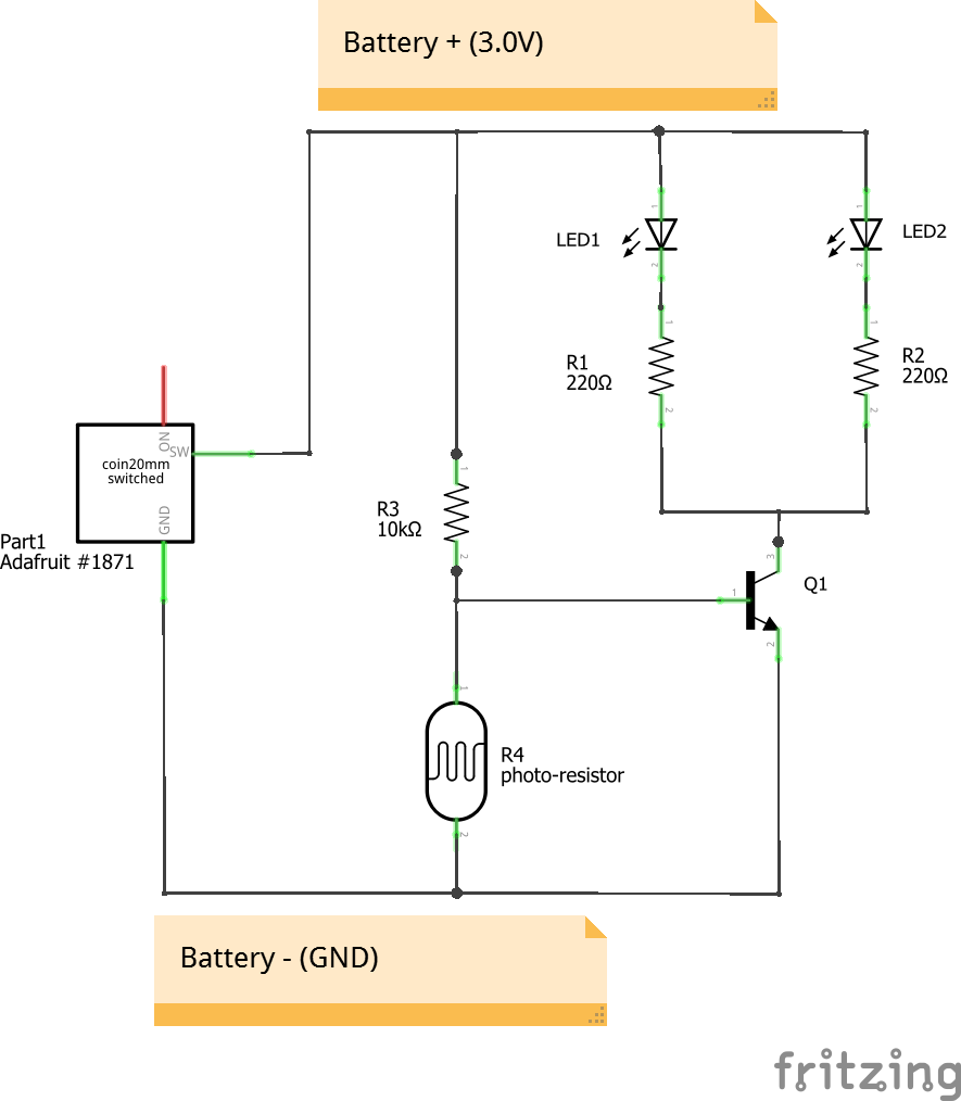
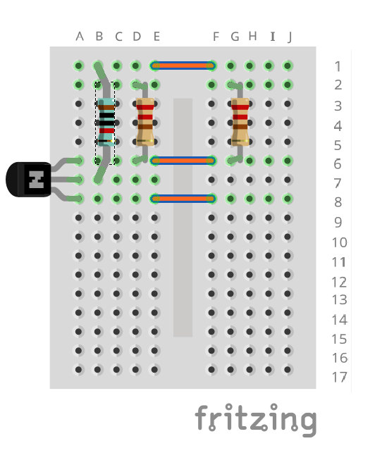
This circuit is based off of Sparkfun's Weevil Eye, which is a great learn-to-solder kit.  We wanted to make it more accessible to students and learners in the time of COVID, and make it a do-at-home project that didn't require any special tools or skills.

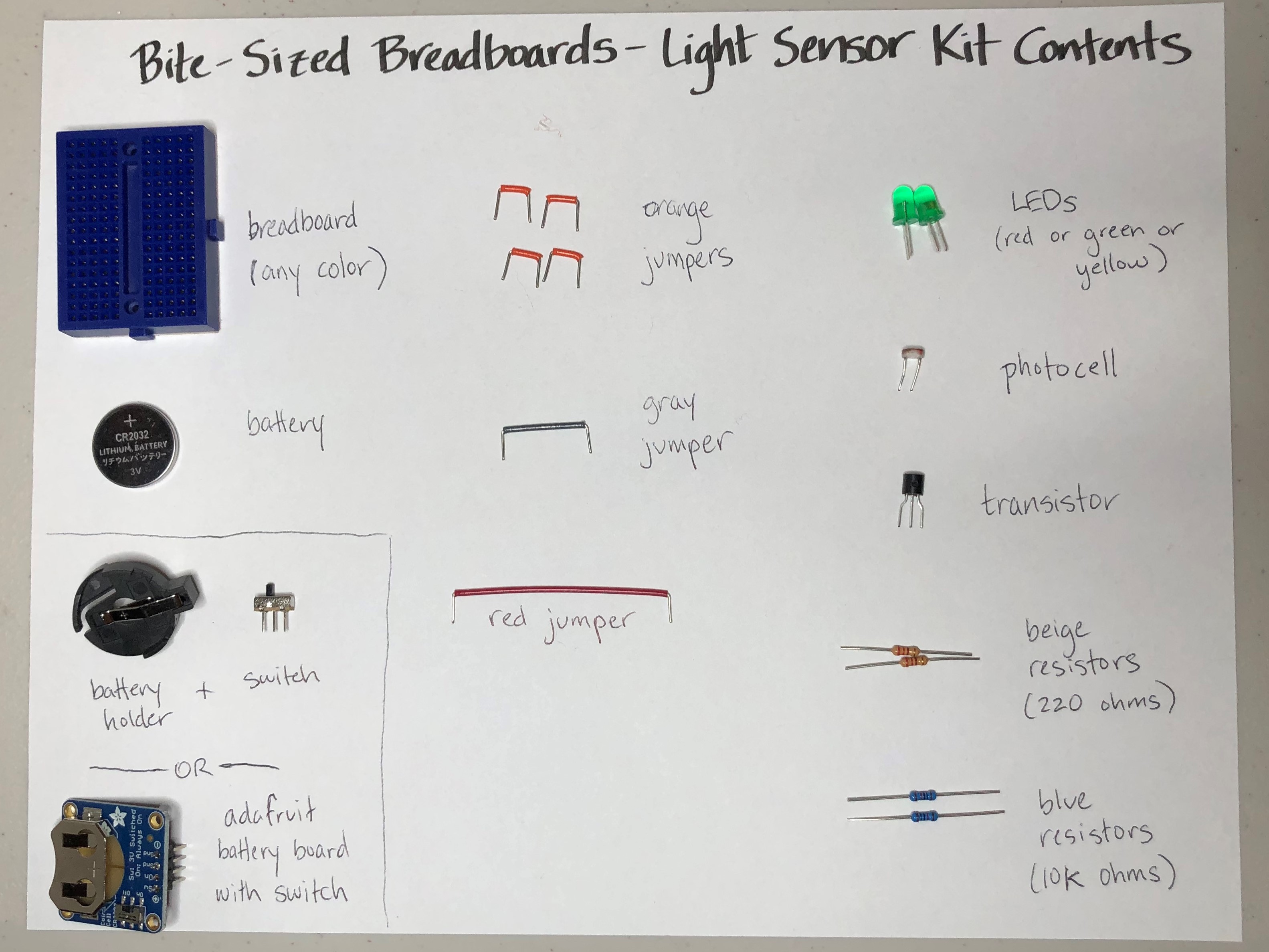
We kitted these up for our local San Luis Obispo STEAM Ahead Camp for young women, which was happening virtually, so each student would have a kit at home and put them together via a video meeting.  We used Adafruit's battery breakout board with a switch to make plugging the battery into the breadboard easy, and that did require soldering a 4-pin header prior to kitting it up.  We're working on finding a suitable CR2032 battery holder than plugs straight into a breadboard, to make it truly no soldering required.  We also cut the legs of the LEDs, photocell, transistor, and resistors to length before kitting, so that students wouldn't need any tools (no cutters, no pliers).

How does it work?  Check out the tutorial in our Project Logs.

LightSensorBOM.csv

All the parts you need, with some alternates, both Adafruit and Digi-Key part numbers so you can order from either place.

ms-excel - 3.68 kB - 09/13/2020 at 00:45

Download

BSB-LightSensorKitContents.jpg

When printed full-size, it's a "placemat" for the kit, showing all the contents.

JPEG Image - 731.22 kB - 08/19/2020 at 04:16

Preview
Download

BiteSizedBreadboard-LightSensor.pdf

Printable instructions - single sheet if printed duplex

Adobe Portable Document Format - 833.92 kB - 07/20/2020 at 21:24

Preview
Download

LightSensor4_schem.pdf

Schematic from Fritzing

Adobe Portable Document Format - 295.36 kB - 07/18/2020 at 22:15

Preview
Download

LightSensor4.fzz

Fritzing file for the finished board, includes schematic

fzz - 23.69 kB - 07/18/2020 at 22:13

Download

  • Troubleshooting

    Alpenglow Industries09/13/2020 at 00:40 0 comments

    Help, my circuit isn't working!  I know, it can be very frustrating.  Take a deep breath and start double-checking - there is always a reason and you CAN fix it!

    If the eyes don't come on:

    1. Make sure the LEDs are pointing in the right direction.  It can be very hard to see which side is the flat side - make sure this is pointing "down", or toward row 2.
    2. Make sure the transistor is pointing in the right direction.  When looked at from above, it should look like a backwards "D".  The flat side of the "D" should be on the right.
    3. Make sure the battery is installed properly, + side up.
    4. If you're using a separate battery holder (not the blue adafruit board), make sure it's fully pushed into the breadboard.
    5. Make sure the switch is switched to the ON position.
    6. Make sure all components are in the right holes.
    7. Make sure all components are pushed all the way in.
    8. If you're outside or in a very bright room, it can be hard to block enough light with just your finger on the photocell.  Try going into a darker or shady space, or holding it against your body with your hands wrapped around it to keep light out.

    If the eyes are always on:

    1. It's probably that you're in a dark space!  Try shining a light directly on the photocell, or try taking the circuit outside.  If the lights go off, you're set!  
    2. If the lights still stay on - go through the list above.

    Help!  I bent a leg on a jumper or component and now can't get it into the hole.

    1. This happens!  First try straightening it out with your fingers.  Be gentle with the components (resistors, photocell, transistor), their legs are a little delicate and you should be able to straighten them easily.  For the orange jumeprs, be a little more forceful, you can try pinching your fingers together and pulling them down the length of the pin to straighten it.
    2. If that doesn't work, ask someone to borrow a pair of pliers!  This will definitely do the trick.

  • How it Works

    Alpenglow Industries09/13/2020 at 00:34 0 comments

    This is the circuit created.  This explanation is geared towards beginners, who aren't already familiar with current flow or how transistors work, so it is a simplification.  

    The LEDs are the lights, the R's are resistors, R4 is the photocell (a light-sensitive resistor), Q1 is the black 3-legged transistor, and Part 1 is the battery holder plus switch.  

    When the switch is off, the positive battery voltage is disconnected and nothing happens.  Negative battery voltage is always connected, but without also connecting positive, no current flows and nothing happens.

    When the switch is turned on, positive battery voltage is connected, current flows out of the "SW" pin and to the rest of the circuit.  The LED's and their resistors get positive voltage from the battery, but negative is turned on or off by the Q1 transistor.  Negative voltage is connected to the bottom pin of Q1, but whether or not the bottom pin and the top pin of Q1 are connected together internally, depends on the voltage at the left pin (the base).  If the voltage on the base is above 0.6V, current flows into the base of the transistor, and the top and bottom pins are connected, which makes the LEDs connected to negative battery voltage, and the "eyes" turn on.  If the voltage on the base is less than 0.6V, no current flows into it, and the top and bottom pins are disconnected, which means the LED circuit isn't connected to negative battery voltage, and so the LEDs turn off.  Again - when the base is above 0.6V, the whole circuit is connected and the LEDs are on.  When the base is below 0.6V, then it's disconnected, and the LEDs are off.

    What controls the voltage on the base?  A combination of R3 and R4.  Together, they make a voltage divider, so the voltage at the point in between them, which is also connected to the base of the transistor, is somewhere between positive battery voltage and negative battery voltage (really the "negative" terminal of the battery is at zero volts, and it's also called "Ground" or "GND").  With a coin cell battery, this means that middle voltage is between 3V and 0V.

    Where in the middle depends on R4, our photocell.  When there's a lot of light present, our photocell has a very small amount of resistance, so the middle voltage is under 0.6V.  When it's darker, it has much more resistance, and the middle voltage goes above 0.6V.  

    So, to put it all together - when it's light, photocell resistance is small, and the middle voltage is under 0.6V.  Middle voltage is connected to the base of the transistor, and under 0.6V, the top and bottom of the transistor are not connected together, so the LEDs are off.  When it's dark, photocell resistance is large, the middle voltage is above 0.6V which turns the transistor on, connects the top and bottom legs internally, and the LEDs turn on.  

    You might notice that sometimes the eyes are on but dim, and sometimes they're bright.  This has to do with how dark it is - the darker it is, the more current is pushed into the base of the transistor, and the more current flows between the top and bottom pins.  If it's only a little dark, then less current is pushed into the base of the transistor, and less current flows between the top and bottom pins.  LEDs are bright when more current flows through them, and dim when less current flows through them.

    Is your circuit not working?  Check out our Troubleshooting project log!

  • Prep Work: Making this kit plug-and-play, no tools required

    Alpenglow Industries08/19/2020 at 03:54 0 comments

    I developed this kit for a summer camp that was happening virtually, during the summer of 2020 when COVID-19 prevented in-person classes.  These are the things we did ahead of time, so that no tools were required for the girls to assemble the kits.

    1. If using the Adafruit battery board with switch (preferred), solder the header it comes with to the board.  The long side of the pins and black header should be on the bottom.  In order to prevent the header pins from getting bent during transit, you can ship it plugged into the breadboard (not in its final location, but careful of orientation.  Pins should be in separate rows.)  If you don't have access to a soldering iron, you can use the alternate battery holder and switch parts and plug them straight into the breadboard.  The battery holder legs are short (these had the longest we could find), so it doesn't stay put as well as the Adafruit battery board does.
    2. Cut the photocell legs so that it sits just above the breadboard.
    3. Cut the blue and beige resistor legs a bit shorter as well.
    4. Cut the transistor legs.
    5. Cut the LED legs.  This one is mandatory because LEDs have legs that are 2 different lengths.  The above cuts just make it easier.
    6. Be sure to package the battery in a separate bag (so it doesn't accidentally form a circuit with another component in transit and drain).
    7. Print the single page instructions and the kit contents "placemat".

    You can use alternate parts from the ones in our Bill of Materials, however, we compared many parts, and think these are the easiest and best to use if you don't want the students to need to use wire cutters and pliers.

View all 3 project logs

  • 1
    Unpack Your Kit
    1. Unplug the battery board from your breadboard
    2. Spread out all the parts from the baggie: 
      (there will be an extra orange jumper when you're done)

    Note which side of the LED is flat. (this will be important to know for later)

  • 2
    Place the orange jumpers

    Note: it may be hard to push the pieces in at first.  Don't push them from the middle - they'll bend out of shape!  Push them with your finger directly over each leg.  You may need to gently bend the legs so they fit better.  This is all part of breadboarding!

    1. Place a jumper from E1 to F1
    2. Place a jumper from E6 to F6
    3. Place a jumper from E8 to F8
  • 3
    Place resistors and transistor
    1. Place beige 220 ohm resistor from D2 to D6 
    2. Place beige 220 ohm resistor from G2 to G6.
    3. Place the blue 10k resistor from B1 to B7.
    4. Place the transistor in column A, with legs in rows 6, 7, and 8.  Make sure the flat side of the transistor is on the right!

View all 8 instructions

Enjoy this project?

Share

Discussions

Similar Projects

Does this project spark your interest?

Become a member to follow this project and never miss any updates