 Alpenglow Industries
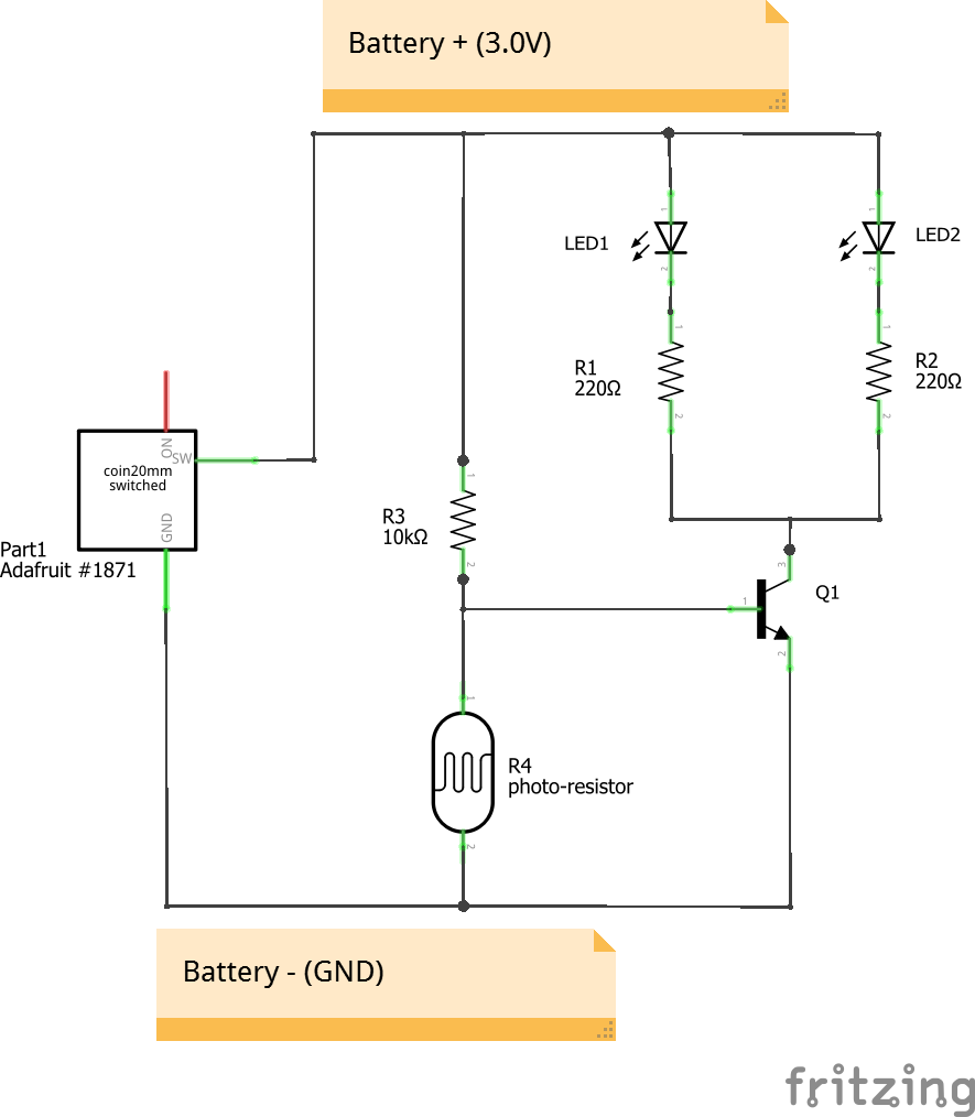
This is the circuit created. This explanation is geared towards beginners, who aren't already familiar with current flow or how transistors work, so it is a simplification.
The LEDs are the lights, the R's are resistors, R4 is the photocell (a light-sensitive resistor), Q1 is the black 3-legged transistor, and Part 1 is the battery holder plus switch.
When the switch is off, the positive battery voltage is disconnected and nothing happens. Negative battery voltage is always connected, but without also connecting positive, no current flows and nothing happens.
When the switch is turned on, positive battery voltage is connected, current flows out of the "SW" pin and to the rest of the circuit. The LED's and their resistors get positive voltage from the battery, but negative is turned on or off by the Q1 transistor. Negative voltage is connected to the bottom pin of Q1, but whether or not the bottom pin and the top pin of Q1 are connected together internally, depends on the voltage at the left pin (the base). If the voltage on the base is above 0.6V, current flows into the base of the transistor, and the top and bottom pins are connected, which makes the LEDs connected to negative battery voltage, and the "eyes" turn on. If the voltage on the base is less than 0.6V, no current flows into it, and the top and bottom pins are disconnected, which means the LED circuit isn't connected to negative battery voltage, and so the LEDs turn off. Again - when the base is above 0.6V, the whole circuit is connected and the LEDs are on. When the base is below 0.6V, then it's disconnected, and the LEDs are off.
What controls the voltage on the base? A combination of R3 and R4. Together, they make a voltage divider, so the voltage at the point in between them, which is also connected to the base of the transistor, is somewhere between positive battery voltage and negative battery voltage (really the "negative" terminal of the battery is at zero volts, and it's also called "Ground" or "GND"). With a coin cell battery, this means that middle voltage is between 3V and 0V.
Where in the middle depends on R4, our photocell. When there's a lot of light present, our photocell has a very small amount of resistance, so the middle voltage is under 0.6V. When it's darker, it has much more resistance, and the middle voltage goes above 0.6V.
So, to put it all together - when it's light, photocell resistance is small, and the middle voltage is under 0.6V. Middle voltage is connected to the base of the transistor, and under 0.6V, the top and bottom of the transistor are not connected together, so the LEDs are off. When it's dark, photocell resistance is large, the middle voltage is above 0.6V which turns the transistor on, connects the top and bottom legs internally, and the LEDs turn on.
You might notice that sometimes the eyes are on but dim, and sometimes they're bright. This has to do with how dark it is - the darker it is, the more current is pushed into the base of the transistor, and the more current flows between the top and bottom pins. If it's only a little dark, then less current is pushed into the base of the transistor, and less current flows between the top and bottom pins. LEDs are bright when more current flows through them, and dim when less current flows through them.
Is your circuit not working? Check out our Troubleshooting project log!
Discussions
Become a Hackaday.io Member
Create an account to leave a comment. Already have an account? Log In.