hIOTron
About Project
Modern Home security systems include complex features such as a fire,temperature,smoke etc. Such a complex systems may be expensive and may not be easily affordable.
In this project we include a solution that include a feature of calling the homeowner on their mobile in case of intruder alert.
Here is the step wise procedure for the same.
1. Working of Arduino GSM home security system
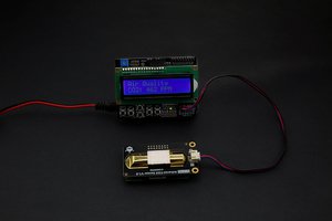
PIR sensor observes motion by sensing the difference in infrared or radiant heat levels emitted by surrounding objects.
The PIR sensor output goes high when it observes any motion. The normal range of a typical PIR sensor is near about 6 meters or about 30 feet.
The PIR sensor has a settling time during which it calibrates its sensor according to the environment and stabilizes the infrared detector.It requires warm up time of 20 to 60 seconds for proper operation of PIR sensor.
In between this time, motion should not be very little to the no motion.If the sensor is not given enough calibrating time, the output of the PIR sensor may not be definitive.
When the PIR sensor detects any motion, the output will be high. This is detected by the Arduino. Arduino then communicates with the GSM module via serial communication to make a call to the respective mobile number which have already Pre-programmed.
The output of the sensor goes low, even when there is motion which may misinform the micro-controller into considering that there is no motion.
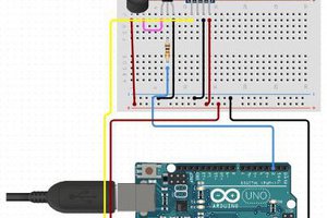
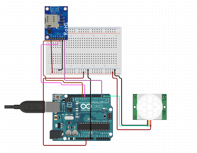
2. Circuit Designing
Since the project is based on an Arduino, the connection is easy. PIR motion -sensor module has a digital output pin. This is connected to any of the digital I/O pins of the Arduino.
The GSM Module interface with the micro-controller in a serial manner. It has an Rx and Tx pins on board itself. These pins are associated with the Tx and Rx pins of the Arduino.
It is essential to note that while uploading the program to Arduino, the GSM module must be disconnected as it might interfere with the serial communication with the Arduino IDE.


 UTSOURCE