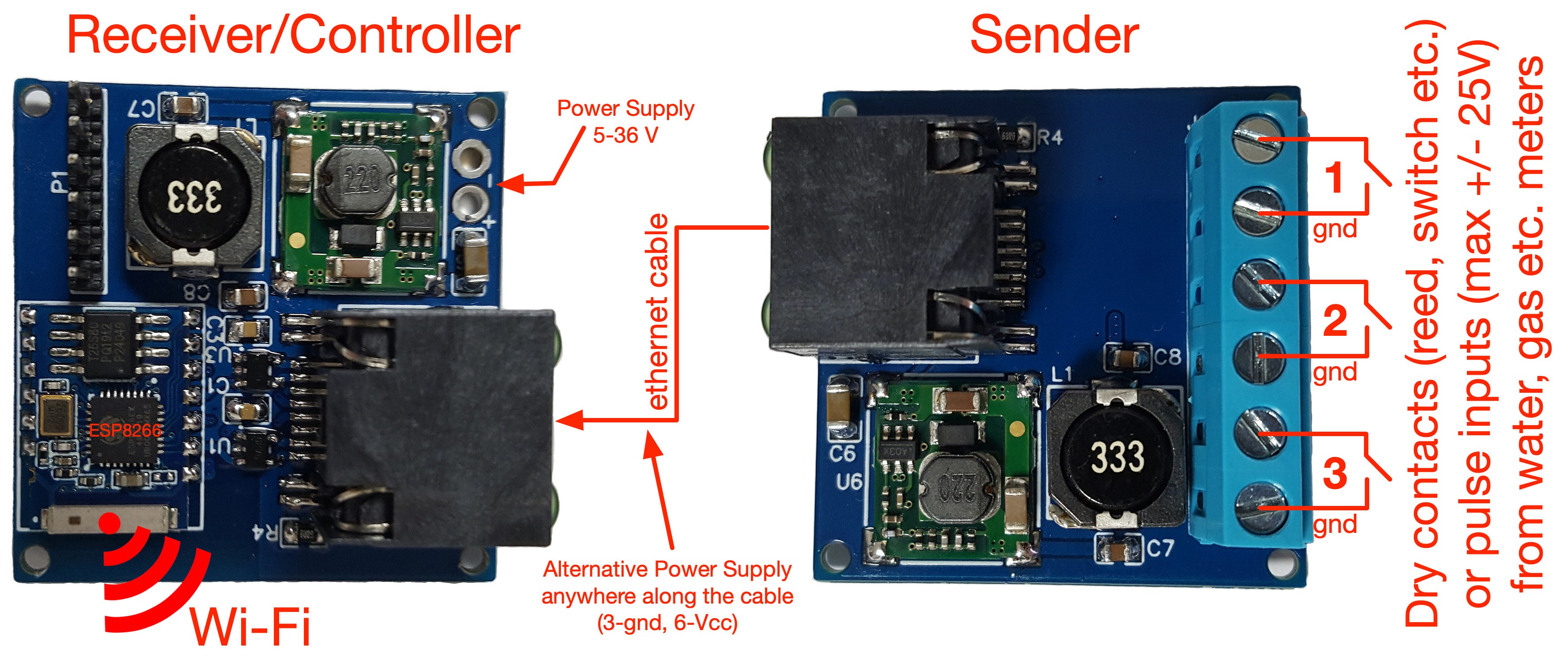
If the wifi signal in your home reaches the meters, you can connect the pulse output of the meters to the sender and keep the receiver/controller close with a short patch cable. If instead the wifi signal cannot reach the meter room, you can use a cable, even very long if necessary, and place the receiver/controller in another room or building where your wifi signal is present.
Sender
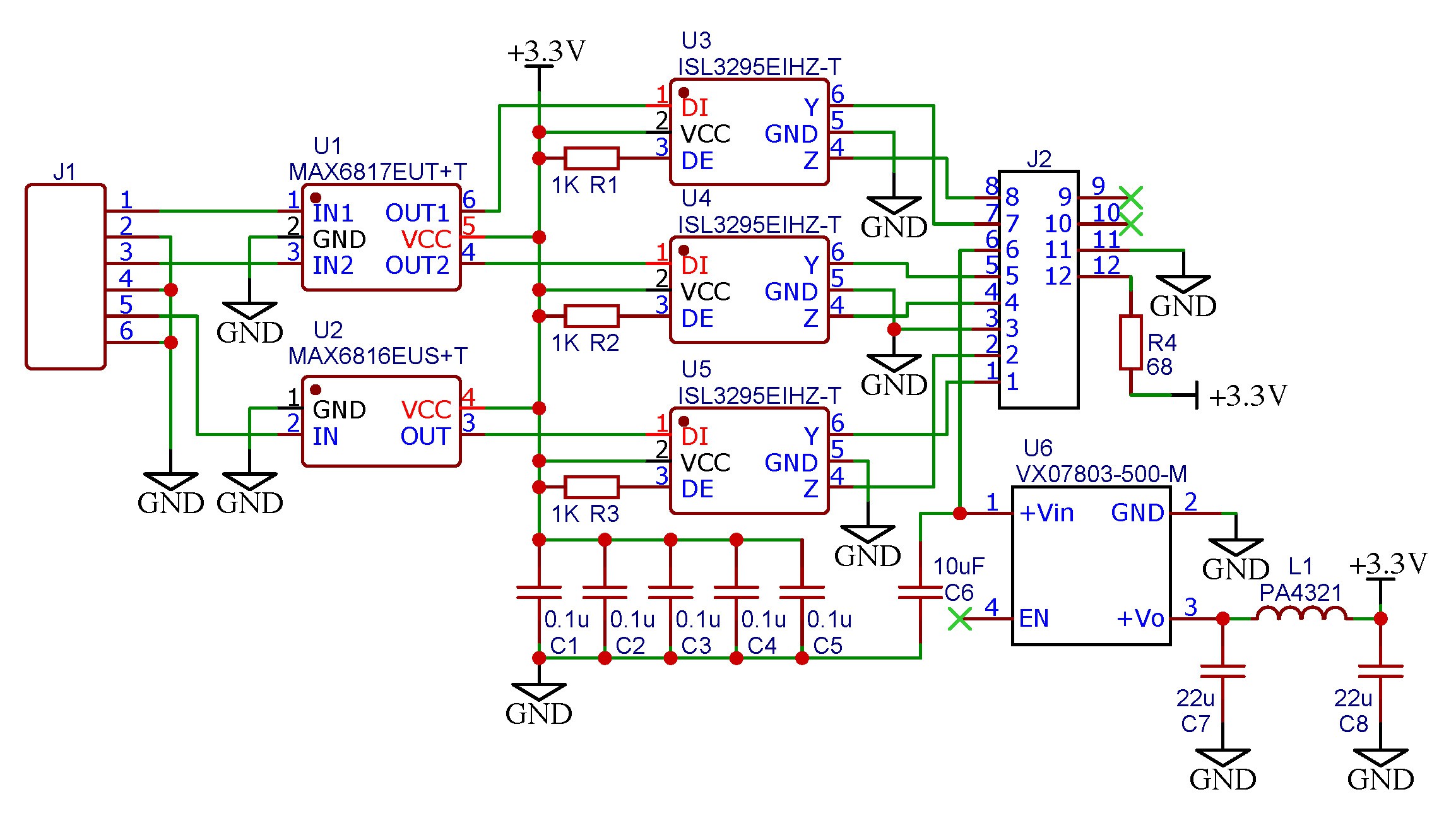
Bill of materials of Sender board
- U1: Maxim MAX6817EUT+T
- U2: Maxim MAX6816EUS+T
- U3, U4, U5: Renesas ISL3295EIHZ-T
- U6: CUI Inc. VXO7803-500-M
- R1, R2, R3: 1K 1/8W SMD 0805
- R4: 68 ohm 1/8W SMD 0805
- C1, C2, C3, C4, C5: Wurth 885012207098 0.1uF MLCC SMD 0805
- C6: Taiyo Yuden UMK316BBJ106KL-T 10uF MLCC SMD 1206
- C7, C8: TDK C2012X5R1A226K125AB 22uF MLCC SMD 0805
- L1: Pulse Electronics PA4321.333NLT
- J1: Cui Devices TB006-508-06BE 6 pin terminal block
- J2: Amphenol RJCSE-5085-01 RJ45 SMD connector
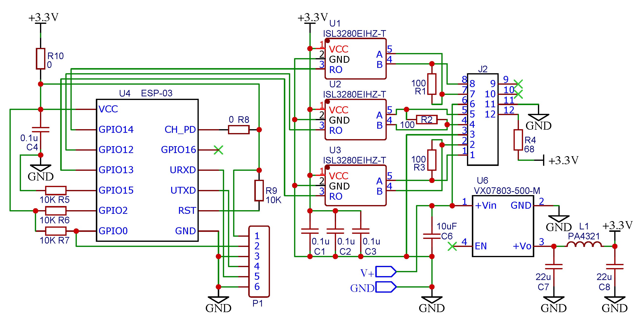
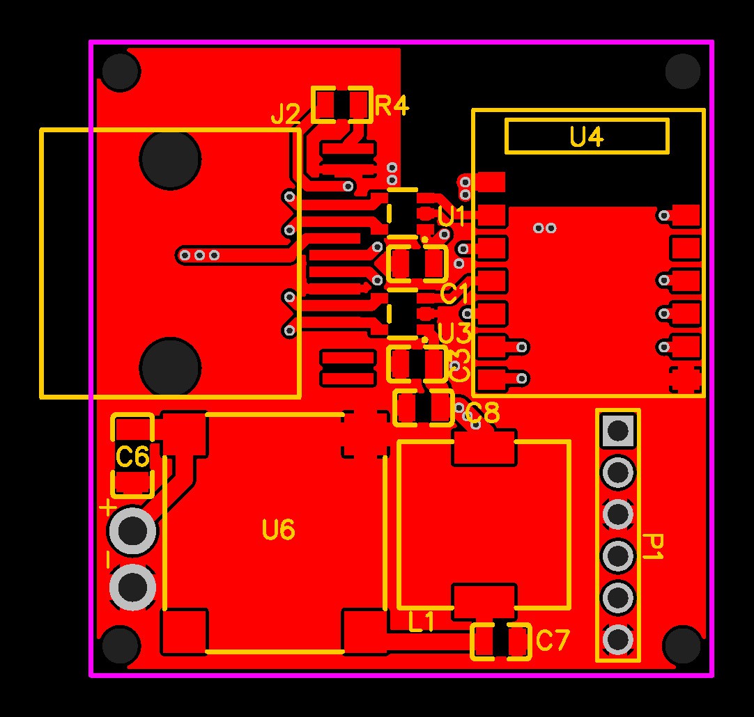
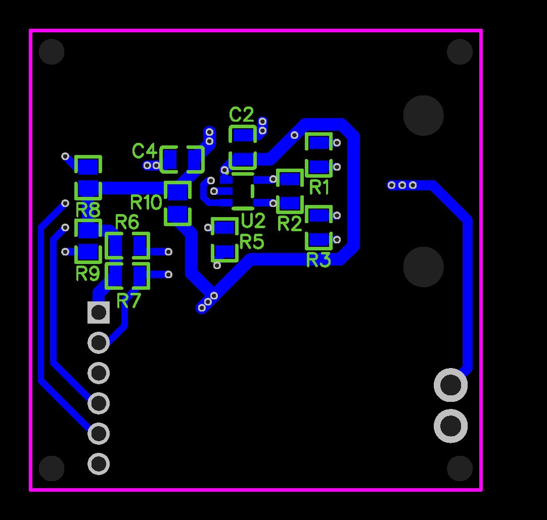
Bill of materials of Receiver/Controller board
- U1, U2, U3: Renesas ISL3280EIHZ-T
- U4: ESP-03 1MB flash ESP8266 controller
- U6: CUI Inc. VXO7803-500-M
- R1, R2, R3: 100 ohm 1% 1/8W SMD 0805
- R4: 68 ohm 1/8W SMD 0805
- R5, R6, R7, R9: 10K 1/8W SMD 0805
- R8: 0 ohm solder joint
- R10: 0 ohm solder joint
- C1, C2, C3, C4: Wurth 885012207098 0.1uF MLCC SMD 0805
- C6: Taiyo Yuden UMK316BBJ106KL-T 10uF MLCC SMD 1206
- C7, C8: TDK C2012X5R1A226K125AB 22uF MLCC SMD 0805
- L1: Pulse Electronics PA4321.333NLT
- P1: 6 pins header 2.54mm
- J2: Amphenol RJCSE-5085-01 RJ45 SMD connector
The 6 pins header P1 is used to connect an external FTDI programmer to flash the ESP8266 firmware. The pinout is:
- 1: 3.3V
- 2: GPIO0 (connect to pin 3 with a jumper to enter flash mode)
- 3: GND
- 4: TXD
- 5: RXD
- 6: GND
The GPIO assignment of the ESP8266 is:
- GPIO14: Pulse Input 1 (counter1)
- GPIO12: Pulse Input 2 (counter2)
- GPIO13: Pulse Input 3 (counter3)
Using the Tasmota firmware, integration with home automation is very simple thanks to the MQTT protocol.
The Tasmota configuration template for PulseTAC is the following:
{"NAME":"Smart Meters","GPIO":[0,0,0,0,0,0,0,0,43,44,42,0,0],"FLAG":15,"BASE":18}


 Solderking
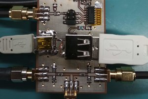
 MS-BOSS
Hi
As I see you use Ethernet cable like UART interface. Isnt It?