 Akshay Baweja
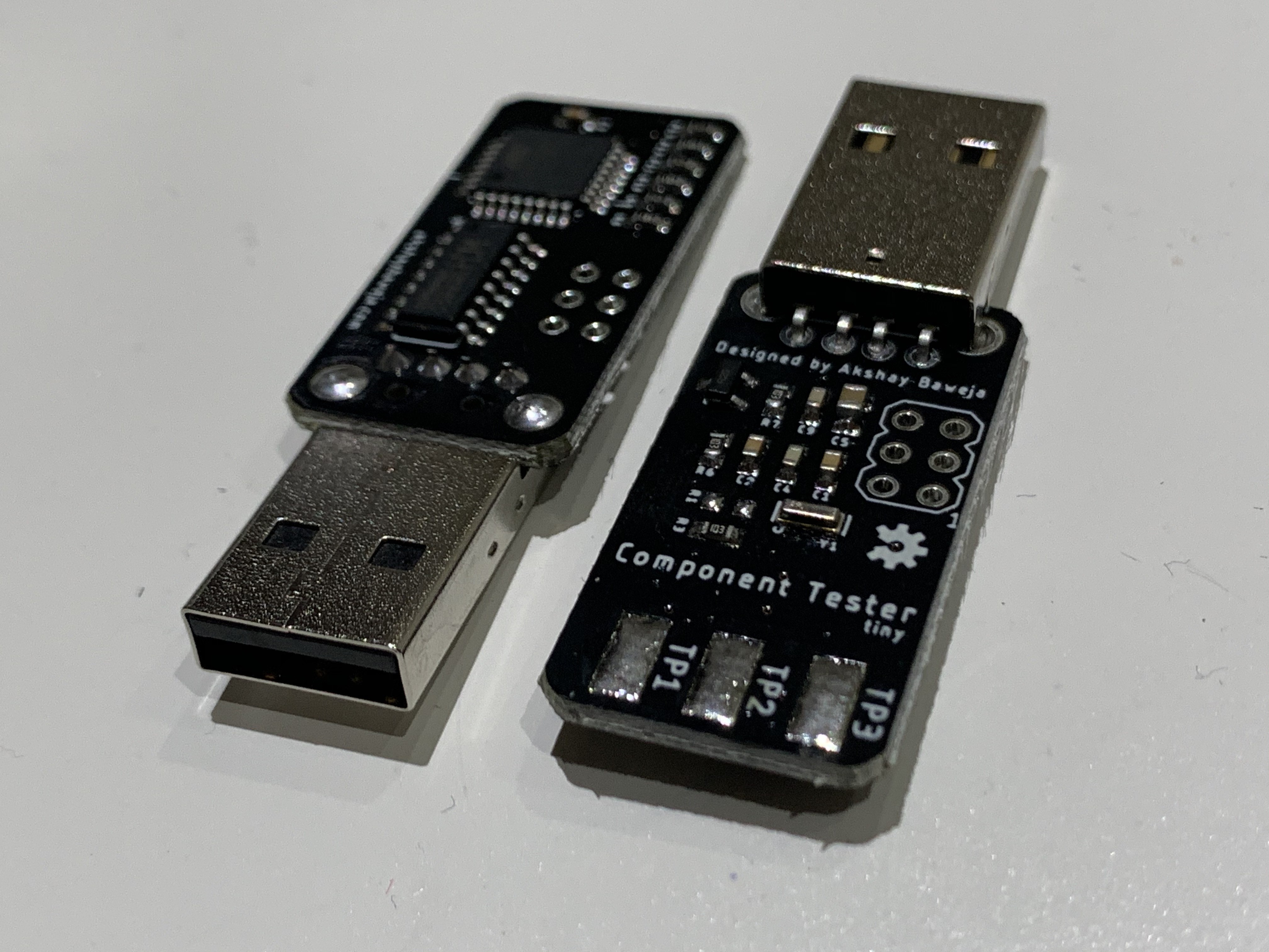
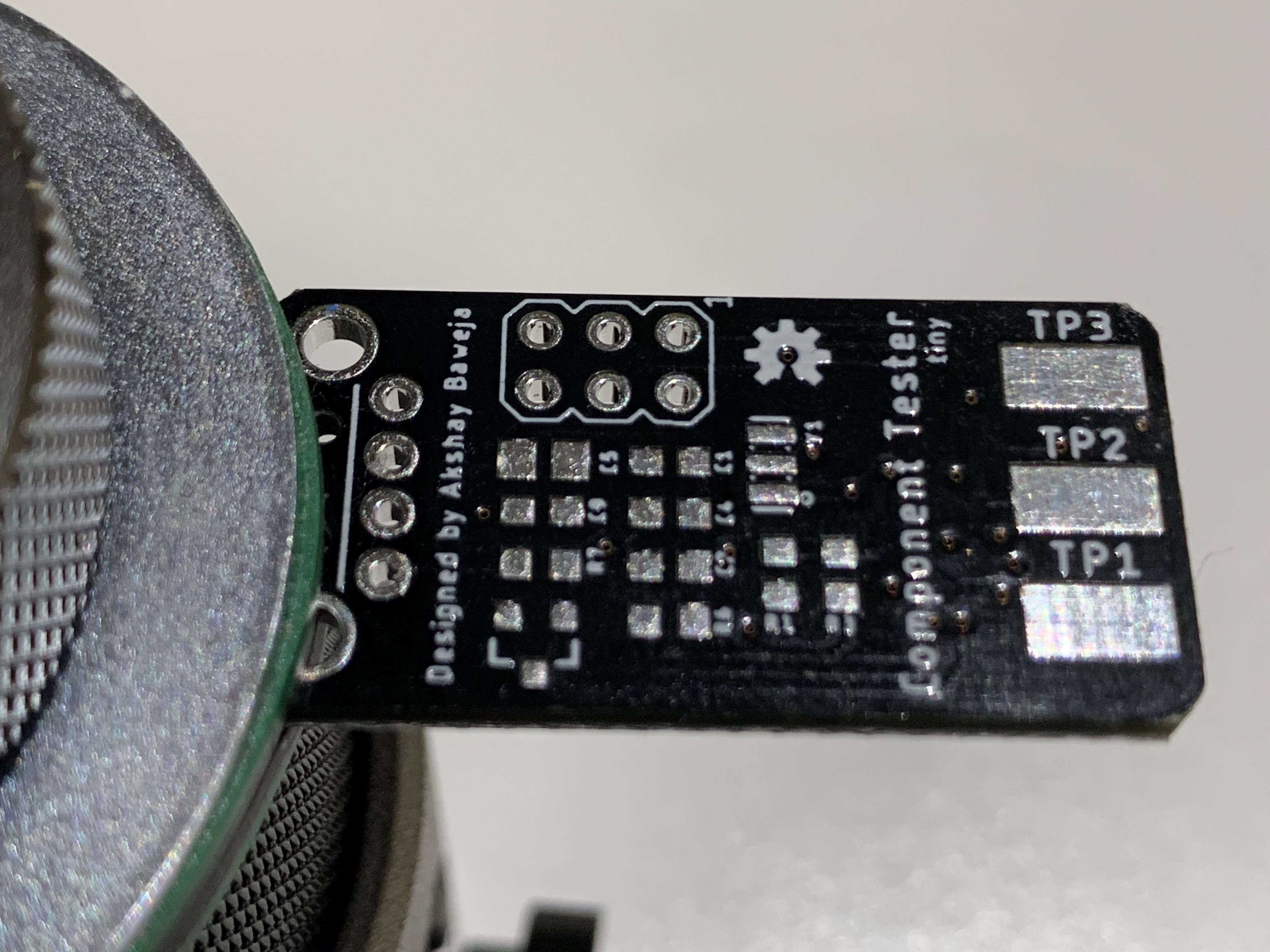
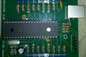
Being an electronics engineer, I always wanted to have a portable component tester, which could test every electronic component out there. In 2016, I built myself a Component Tester based on AVR TransistorTester by Markus F. and Karl-Heinz Kübbeler. Following that, I redesigned the Component Tester to size of a keychain.
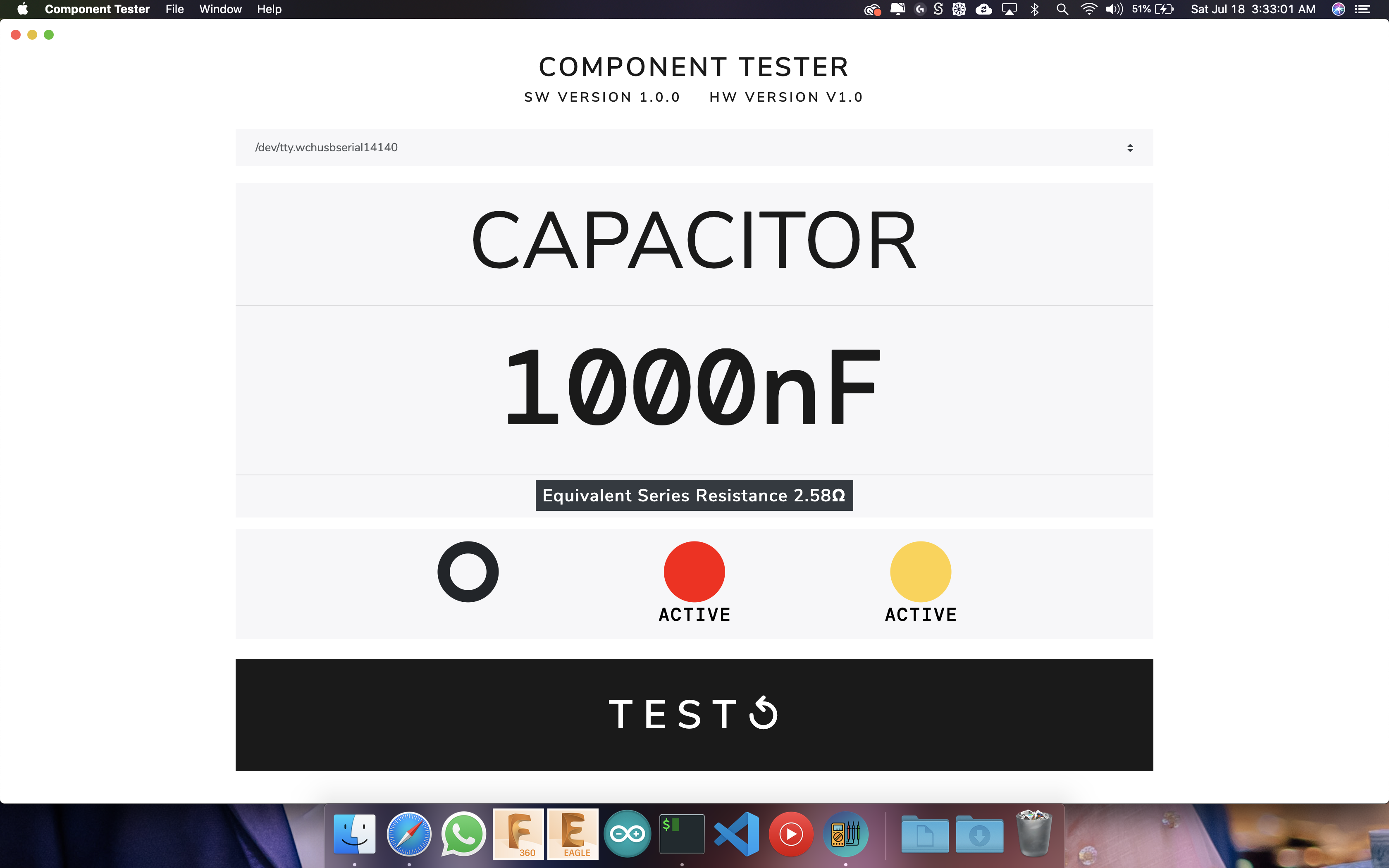
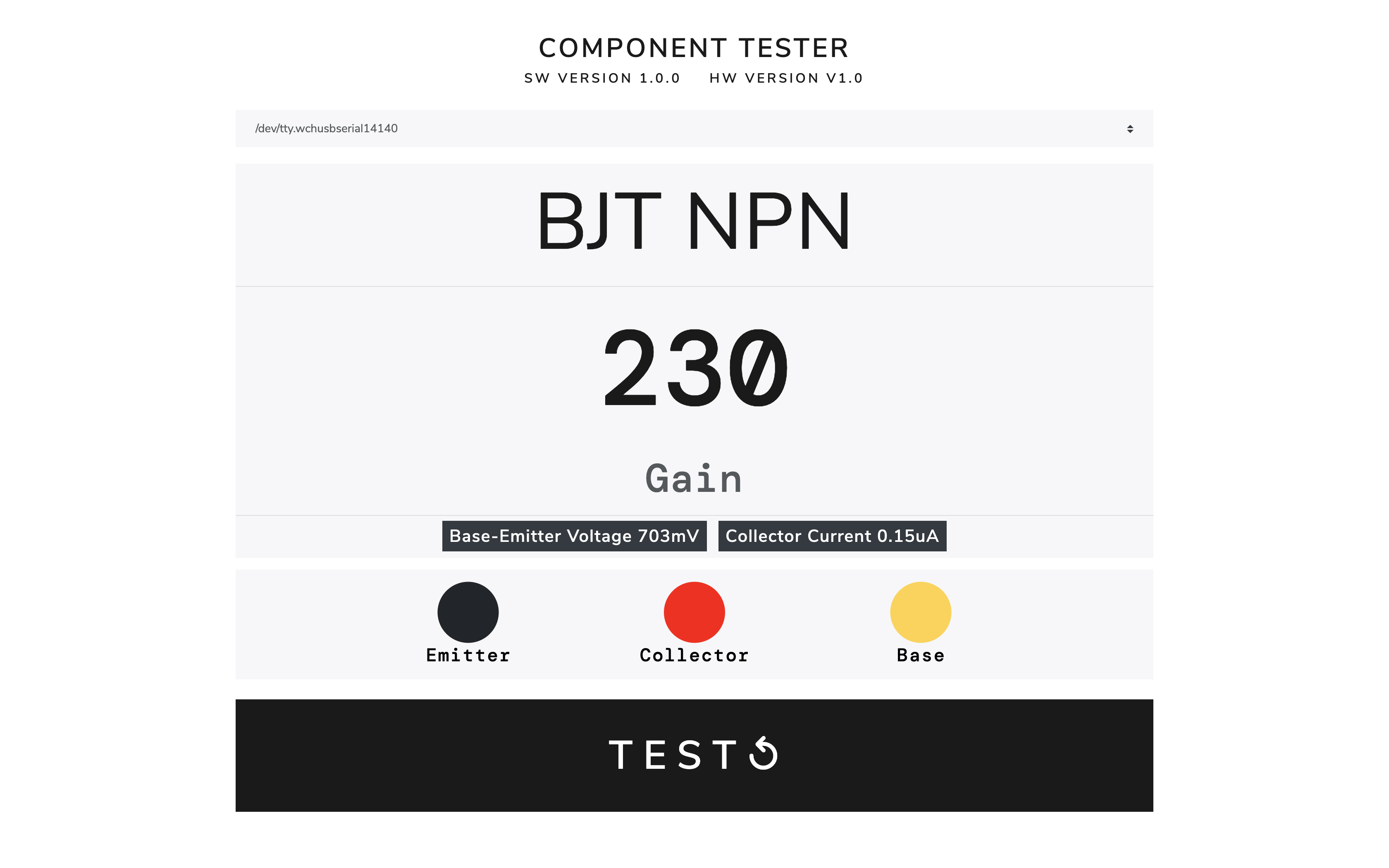
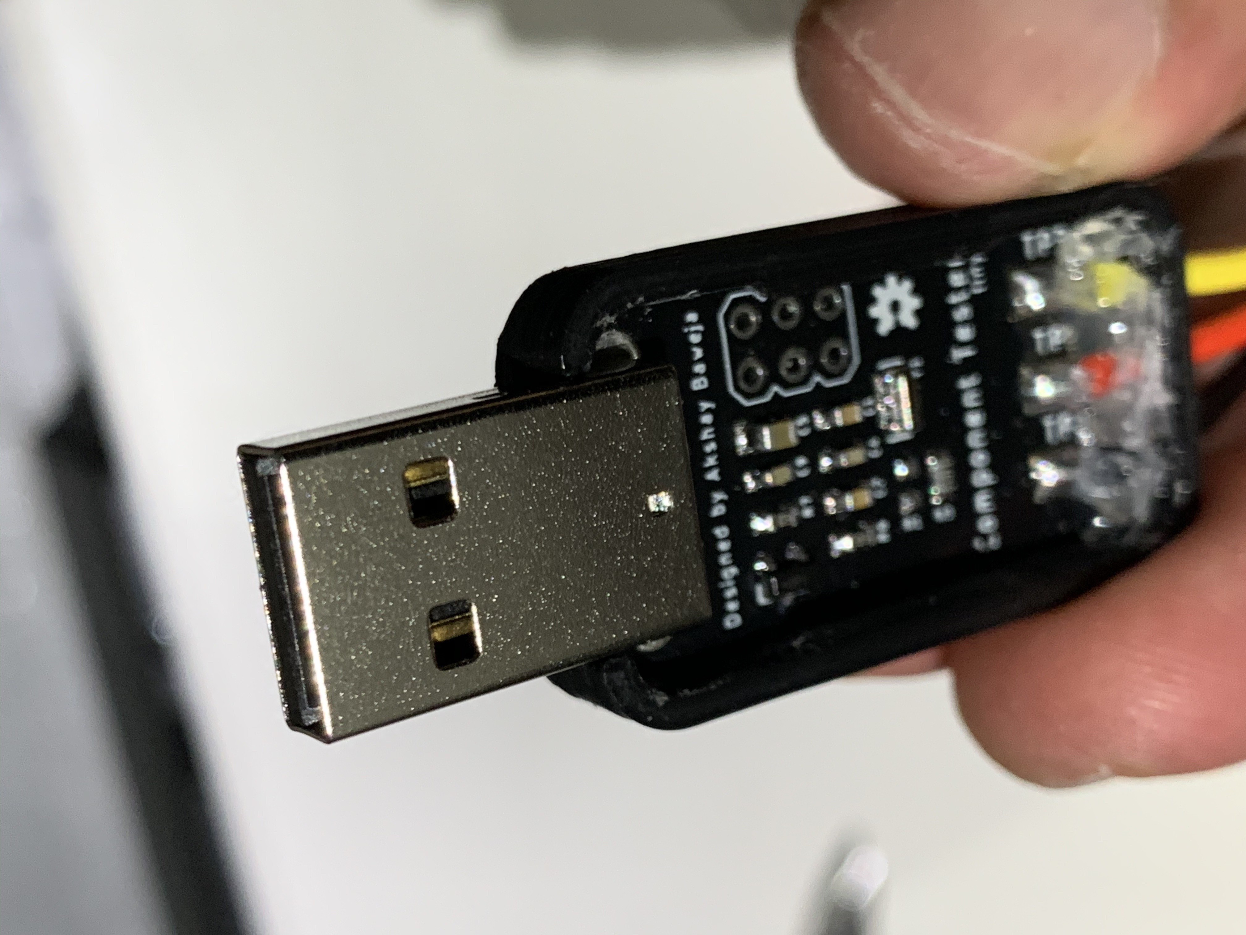
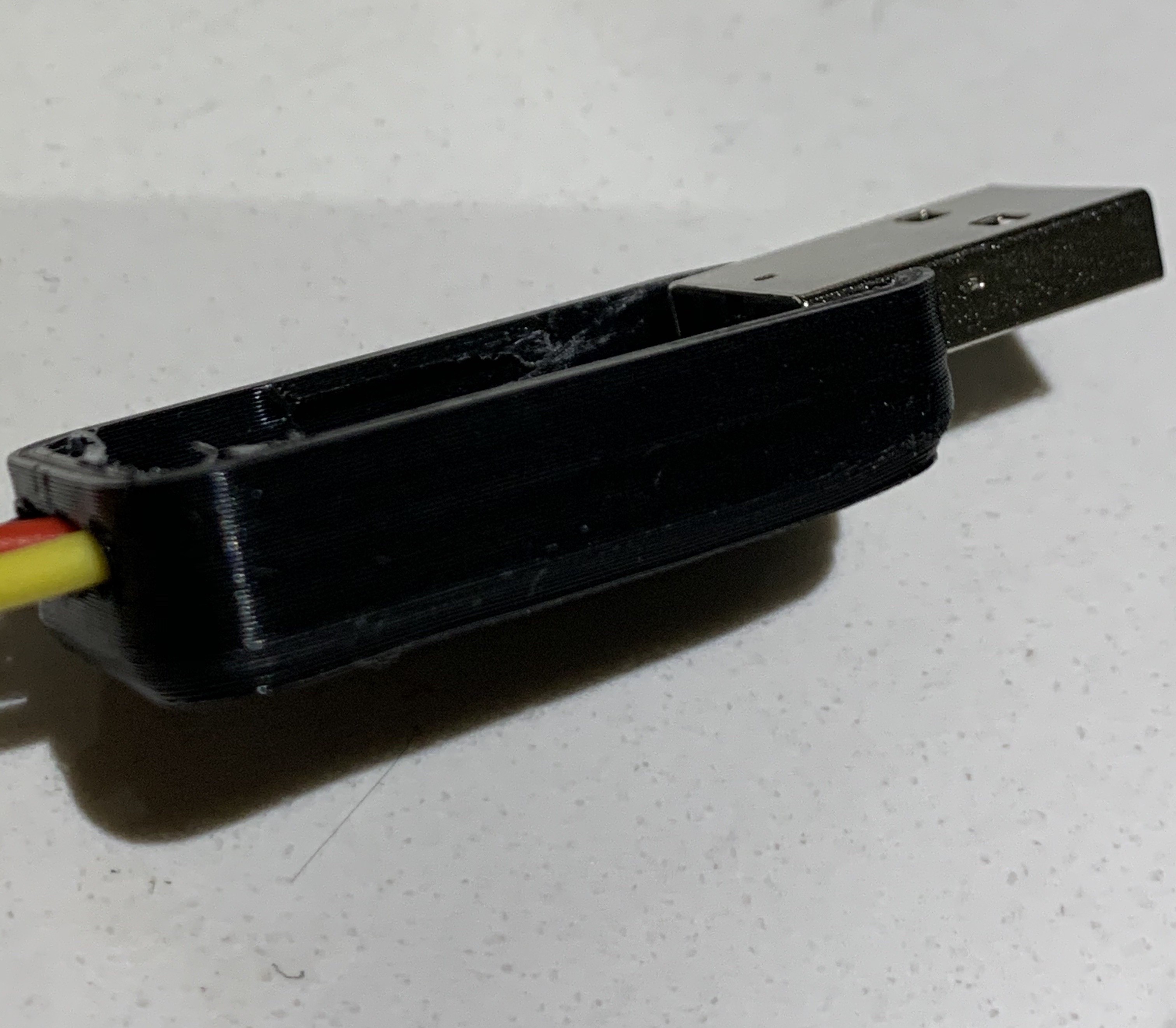
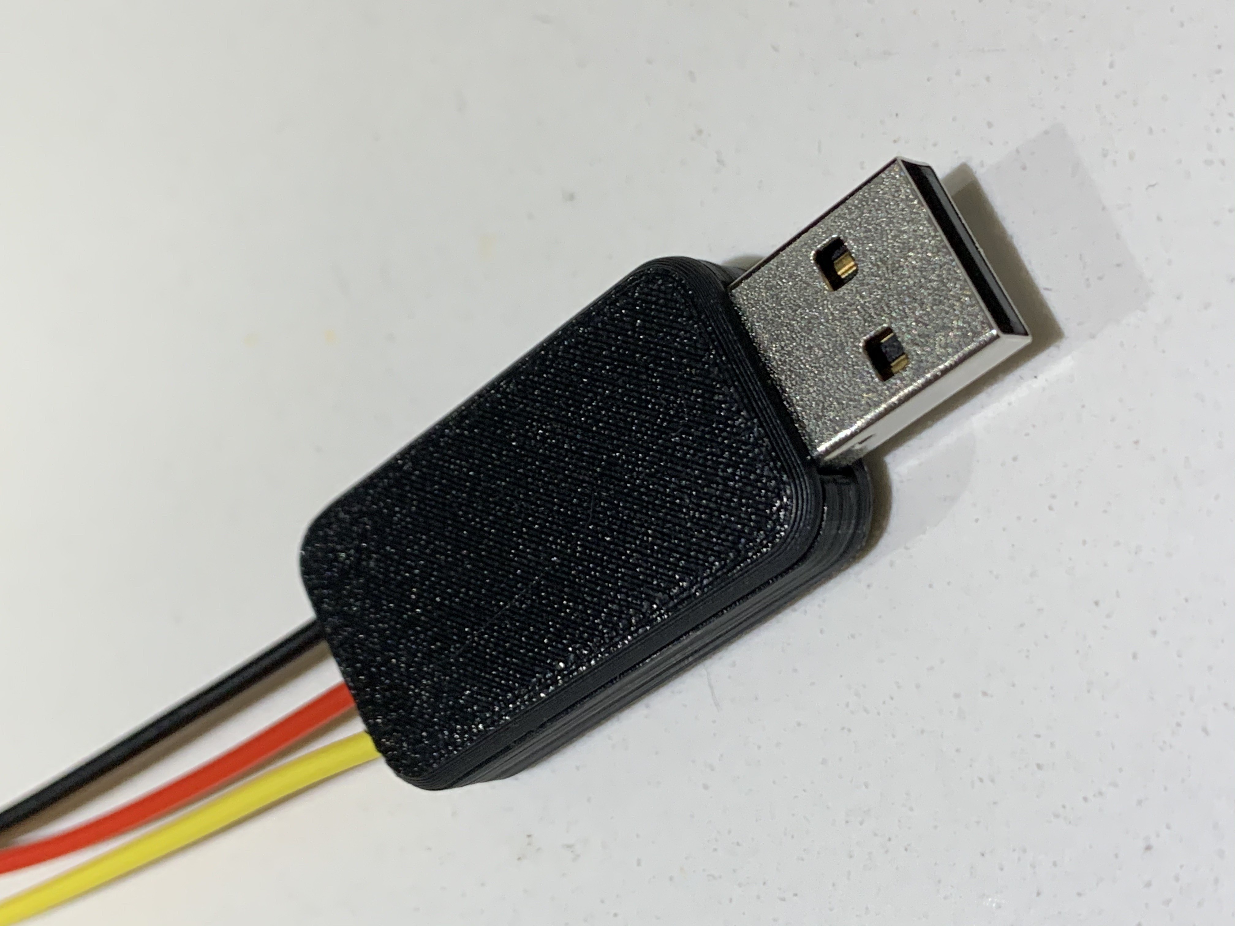
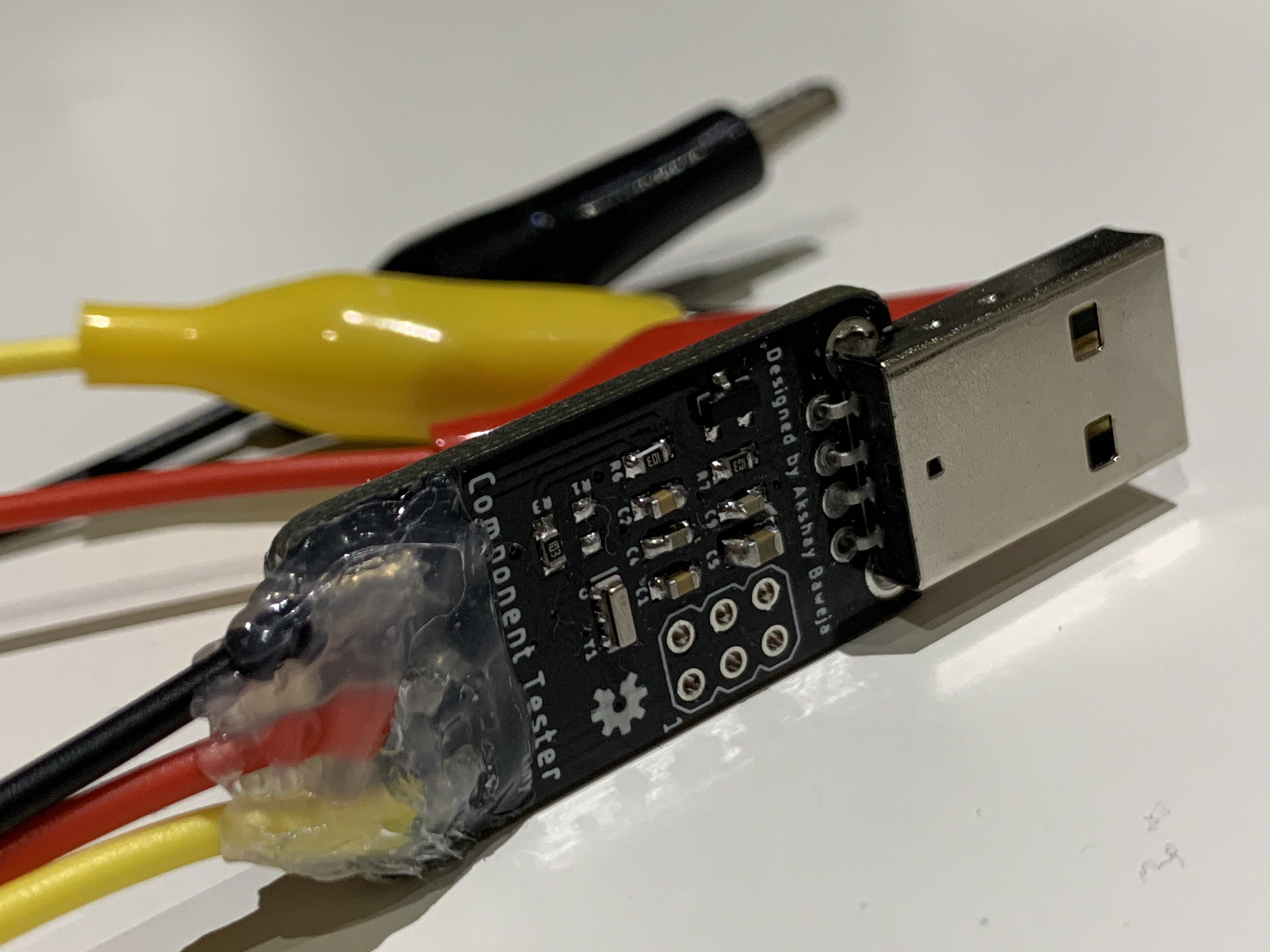
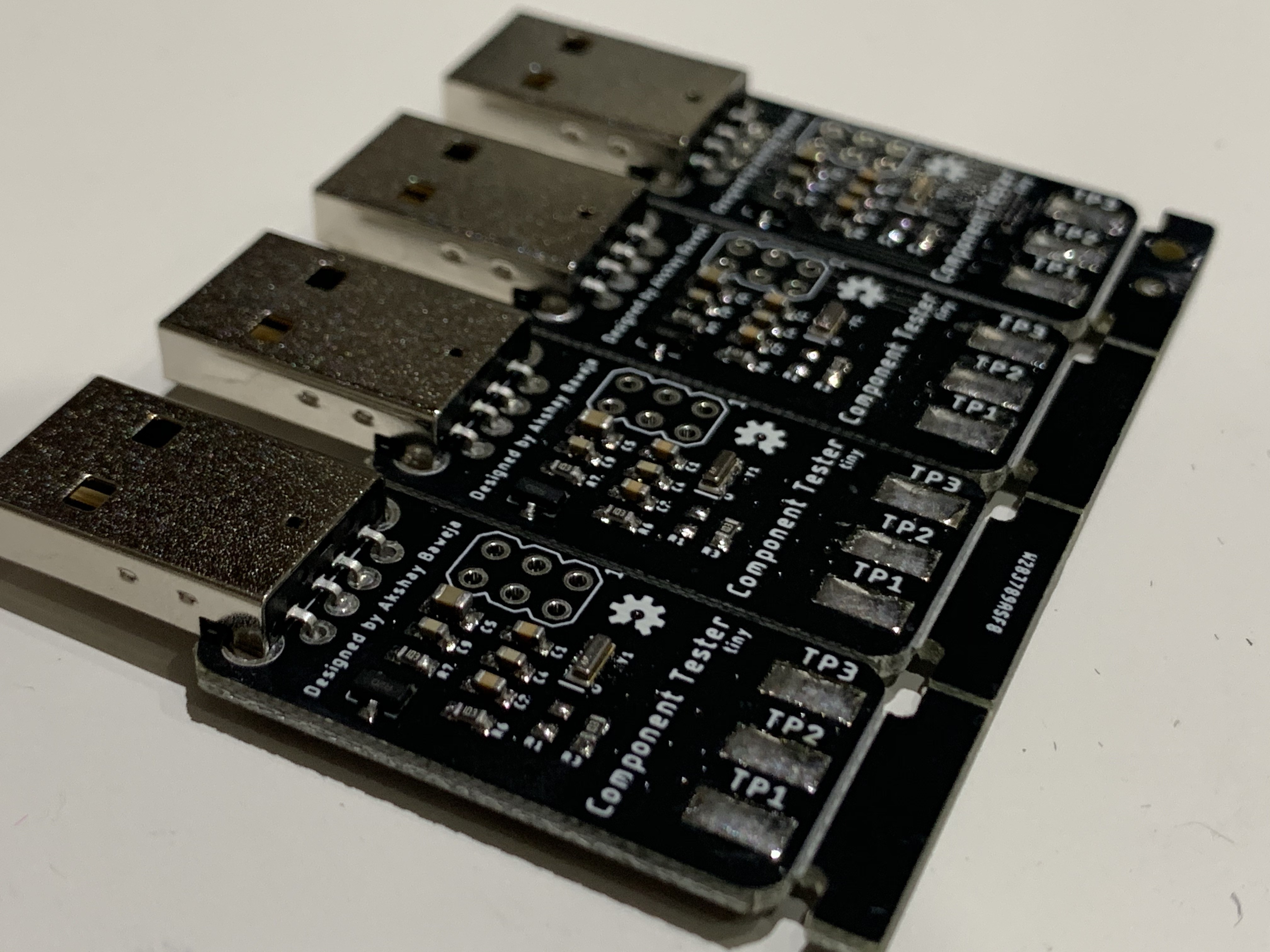
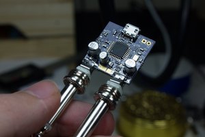
Since makers, engineers and hobbyists have a computer around our work-desk always. So I thought to myself why not build a component tester that could be used as a USB accessory which allow us to test the components. I have designed a software to go along with the USB component tester that displays the required test parameters on display in a minimal design form. The test leads are colour coded and these colours indicate the pin configuration. The software supports three major OS platforms macOS, Windows and Linux.
Supported Components
- Resistor
- Capacitor
- with ESR
- Inductor
- Diode
- Transistor
- BJT
- UJT
- PUT
- FET
- JFET
- MOSFET
- IGBT
- TRIAC
- Thyristor


 Jacob Creedon
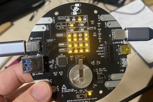
 Spencer Maroukis
 zittware
I made a copy, and it turned out that this problem occurred. I checked all the hardware and there is no problem. I also checked that the firmware and fuse position are correct and there is no problem. Please help me, thanks!
After running the desktop software for the first time to select the port, the software does not display the "Test" button or the hardware version, and then reselect other ports and return to the correct tester port, prompting "Serial port error open COM2: Access denied"