Close
0%
0%

Battery Low-Voltage Cutoff

Don't kill your rechargeables.

Public Chat
Similar projects worth following
I'm knocking together a gadget to run 12V devices off of 18V Ryobi One+ battery packs (of which I have a few). I found a sufficiently beefy buck converter a while back that knocks 18V (nominal) down to 12.6V, but there's nothing in it to keep the battery from being discharged too much. This circuit will cut off its output at around 14.28V...2.86V per cell for Li-ion, 952 mV for NiCd (since I still have some of those).

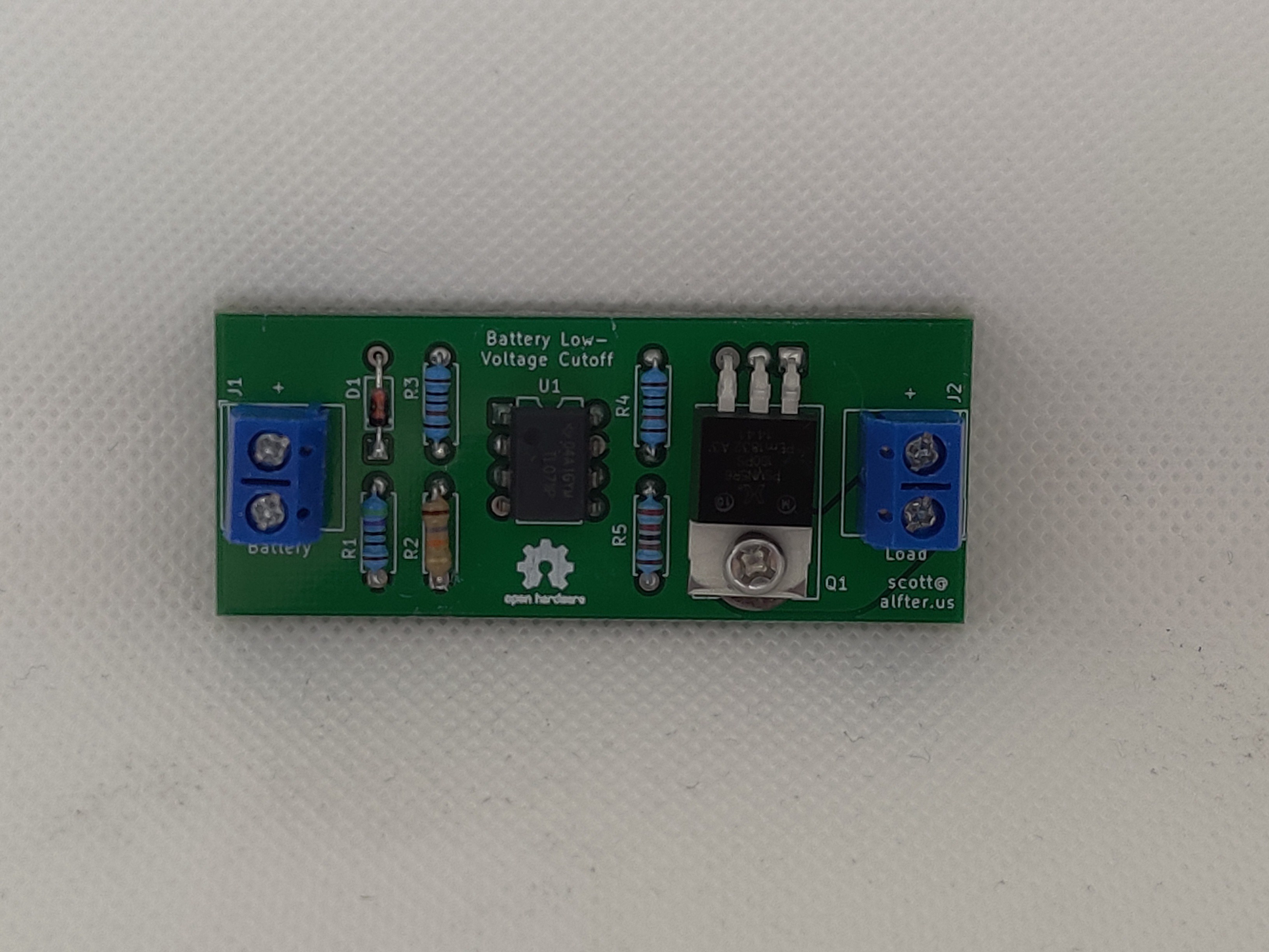
It's a fairly simple circuit.  The input voltage feeds both a voltage divider and a 5.1V reference, which are compared by an op-amp.  If the input voltage exceeds 14.28V (set by the 18k and 10k resistors in the voltage divider), the op-amp turns on the MOSFET, which turns on the load.  Since a freshly-charged Li-ion battery pack can exceed the MOSFET's 20V gate-to-source rating, the gate is driven through another voltage divider.

(The idea is largely cribbed from http://circuitdiagram.org/low-battery-voltage-cutoff-or-disconnect.html, but with the bipolar transistor and relay replaced with a MOSFET.)

  • Coming soon to Tindie

    Scott Alfter11/24/2022 at 23:40 0 comments

    I've built up three more with the parts I had on hand.  They'll be available for purchase once Tindie signs off on it.

  • Maybe I should build a few more of these

    Scott Alfter08/11/2022 at 07:18 2 comments

    I just put a project up on Tindie for the first time...but not this one.  Of that other project, I had JLCPCB build 5, but I probably only need one for myself, so that's 4 that are ready to go.  This, however, seems to be my most popular project.  I still have plenty of boards, and I think I ordered enough parts at the time to build a few more.  It's a simple circuit with a low parts count that I could assemble myself fairly quickly.

    As for how the one board I built is holding up, I basically have two use cases for the battery adapter I built.  One is to run a 12V tire inflator to top off car and bicycle tires.  The other is to power a 300W inverter, which in turn runs the built-in inflator (which doesn't pull the full 300W, but it wouldn't even start on a 120W inverter I keep in my car) on an air mattress I bring on camping trips.  If I had to guess, they both present non-trivial loads at 12V, but the MOSFET I chose has been up to the task.

  • Boards arrived today

    Scott Alfter08/12/2020 at 04:25 0 comments

    15 days to get here from JLCPCB, and that was with the cheaper shipping option.  When I got home, I pulled the parts off the breadboard, stuffed them into one of the PCBs (panelized 3-up, so I received 15 total), and hooked it inline between a Ryobi NiCd battery pack and a buck converter...and it worked!

    Now I need to work on the packaging to turn all of this into a durable adapter that I can bring on the road with some battery packs...might need to start another project for that.

View all 3 project logs

Enjoy this project?

Share

Discussions

John L. wrote 11/16/2021 at 16:12 point

Does this circuit turn itself completely off to prevent parasitic drain on the battery?

  Are you sure? yes | no

Scott Alfter wrote 12/02/2021 at 22:50 point

I didn't provide for that.  I suspect the drain of the opamp is fairly low, but the way I've used mine so far, I usually just plug in a battery pack long enough to run a device (like an inverter to power the inflator on an air mattress) and then unplug it, so I haven't tried measuring no-load drain.

  Are you sure? yes | no

Similar Projects

Does this project spark your interest?

Become a member to follow this project and never miss any updates