 engineerkid1
All electronic devices require power supplies which converts the alternating current into direct current. Almost all the power supplies have a low power factor and introduce harmonic current, even the liner supplies have this issue. Effect of the single power supply may not be significant but in a system where multiple power supplies are used this effect can be considerable. Power factor of the system/ supply can be improved by introducing power factor correction circuits this will also reduce harmonic currents.
SPC7110F is a power factor correction converter IC. It consumes very little power due to the fact that a high voltage CMOS process is utilized in the manufacturing of IC. Many fault protection techniques are also incorporated in the IC.
Features of SPC7011F
- Very Low Standby Power
- High-precision over current protection
- Improved power efficiency at light load
- No Audible Noise at Startup
- Soft-Startup and Soft-OVP functions
- Low current consumption by CMOS process
- Enabled to drive power MOSFET directly
- Output peak current of ± 1000 mA
- Protects the output capacitor by OVP function
- Open/short protection at feedback (FB) pin
- Under-voltage Lockout
- Restart timer
- Standby function
SPC7011F Replacement Part
UCC28019
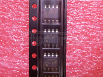
SPC7011F Pictorial View
Pictorial view of the utsource SPC7011F is given below, it is an eight pin IC that is available in SOP package
Pin Description
Pin diagram and pin description of the IC SPC7011F is given below

Pin Number | Pin Name | Description |
1 | FB | Feedback voltage input |
2 | COMP | Compensation |
3 | RT | Set maximum on time |
4 | OVP | Over voltage detection |
5 | IS | Current sense input |
6 | GND | Ground |
7 | OUT | Output |
8 | VCC | Power supply |
IC Electrical Characteristics/ Specifications
Some Electrical characteristic of the device are given below
Parameter | Description | Value |
IVCC | VCC pin current | - |
VCC | Supply voltage | 28 V |
IO | Output current, sink & source | 1000 & -1000 mA |
Vinfb, Vincomp Vinrt, Vinovp | Input voltage FB COMP RT OVP | -0.3 to 5 V |
Iinfb, Iincomp Iinrt Linovp | Input Current FB COMP RT OVP | ±100 µA |
PD | Total power dissipation | 625 mW |
Ta | Operating temperature | -40 to 105 C |
TJ | Junction temperature | 150 C |
Tstg | Storage temperature | -40 to 150 C |
Working Principle
SPC7011F consists of an error amplifier, comparator, chopper circuit, delay circuit and oscillator circuits. This IC performs the power factor correction converter operation by utilizing a boost chopper in critical mode. The switching operation in critical mode is implemented with self-oscillation without any external oscillator. With power factor correction circuits in the critical mod, the switching frequency is always changing due to instantaneous values of the AC input voltage. This switching frequency also changes when the input voltage or load changes. Due to the switching current flowing form built in the inductor, since an inclination of inductor current depends on input voltage and on time is constant, the outline linking peak of the inductor current which becomes the same AC waveform as the input voltage, which enables power factor correction operation.
Applications
SPC7011F can be used in following applications
Power factor correction circuit
Power factor correction circuit using SPC7011F
Circuit diagram of power factor correction circuit is shown in figure below.

Samsung LED LCD TV-UN46EH6000F-Power Supply and Correction Circuit
