 Arno
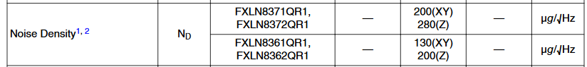
ArnoAfter creating a proof-of-concept with an ADXL337 from Sparkfun and some conditioning with a breadboard, which was super noisy, I went about putting together a schematic for a small PCB. I ended up choosing a FXLN8361Q from Freescale (NXP). Compared to the ADXL337, it does have marginally lower noise density. On Digikey, the price difference between the two is only a few cents.

I wanted to design something that would meet the following criteria:
- output to a 3.5mm audio cable
- be battery powered
- be mic-bias powered
- cheap
I wanted to output to a 3.5mm headphone jack so that I could plug the device into my PC and record some sounds as either a Line-In or Mic-In source. There is a pretty dizzying array of options for microphone pinouts with TRS or TRRS 3.5mm jacks. A fairly common 3-contact TRS pinout for microphones is [Left, Right, Gnd]. I ended up choosing a TRS pinout with a [mono-output, bias-in, gnd] mapping for simplicity's sake. I threw in a summing amplifier with some 1st order low-pass & high-pass filtering. This allows me to have an AC coupled output with some noise reduction and an output resistance of basically 0 Ohms. The FXLN8361's output impedance is roughly 10KOhm. By interposing some 3 pin 1.27mm headers between the accelerometer and the input of the summing amplifier, I can play around with turning on different combinations of the X, Y, and Z directions.
The second design criterion was pretty easy to satisfy. I chose a CR2032 as it's a relatively common button cell battery that has very good capacity compared to other button cells. Furthermore, its discharge curve reduces from 3V to about 2V when it is empty. In order to maximize battery life, I chose the positive power rail to be a linearly regulated 1.8V off of the battery voltage.
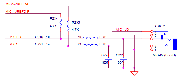
The third criterion was not very easy to meet. Most audio codec ICs can source a very small amount of power from reference voltages that are tied to the input signal lines of the mic-in/line-in connectors via pullup resistors. For example, the Qualcomm WCD9335 that sits in the Pixel 1 phone can source 5uA to 6mA for a mic load. The load regulation & accuracy is seemingly pretty terrible though and the datasheet claims that it can be anywhere between 1V and 2.85V. The current limiting pull-up resistor itself will also effectively degrade the load-regulation. The codec from Realtek that sits on the motherboard of my PC, an ALC887, apparently has an output reference voltage that can be configured for either 2.5V of 3.75V. But, the sourcable DC current isn't specified. Realtek's recommended audio jack schematic shows us what we can expect in terms of a size for these pull-up resistors:
In any case, the FXLN8361Q only consumes about 180uA of quiescent current when powered with 1.8V. The op-amp I chose for some basic filtering, the TLV9001, has a worst case rated quiescent current of 77uA. If the power supply components can all be kept fairly low power, and sufficiently large resistors are used for general pulldowns/pullups and filter components, then the core circuitry should consume < 500uA.
The required negative rail for the op-amp is a linearly regulated output of an inverting charge pump. The inverting charge pump is an apt choice here as it is much more efficient than other switching topologies (e.g. inverting buck) at these low power levels. A charge pump also requires many less external parts which is nice. Since the AC coupled version of the signal cannot be greater than (1/2) 1.8V, it's ok for the magnitude of the negative rail powering the op-amp to be a little smaller than -1.8V. Given restrictions on the drop-out voltage for the linear regulator, I chose the negative rail to sit nominally at -1.453V. The charge pump switches at well above the audible range (30KHz min, 50KHz nom) and the linear regulator following it has a PSRR of about -35dB at these frequencies, so I'm not too worried about switching noise impacting the audio quality. All in all, a quick & dirty spreadsheet I put together indicates that during an active use, the 1.8V regulator will pull about 2mA. This means that, if the codec's bias output is configured for 3.75V, the MIC-bias pullup resistance on my PC's 3.5mm input jack would need to be < 975 Ohms in order to succesfully power the device with the mic bias reference. If the reference schematic above was implemented on my PC's motherboard, and the reference voltage was configured for 3.75V, then the maximum supply current I can tolerate is only about 400uA. I don't have a schematic for my motherboard so I don't know what voltage the reference is configured for or what the pullup resistances are, but my hopes are not high that the mic-bias powering will work. =(.
I was able to meet the cost criterion pretty well. The most expensive part in the design is the accelerometer itself at about $4.6 in low-volume. Somehow, I did manage to splurge a whopping $2.7 on the negative linear regulator - there must be a cheaper LDO that is just as good somewhere. The rest of the parts in the BoM are all less than 1$ a piece and the total BoM cost comes in at about 15$ in LV pricing.
The schematics for this Rev1A design, as well as the power calculation spreadsheet, are attached to this project page.
Discussions
Become a Hackaday.io Member
Create an account to leave a comment. Already have an account? Log In.