 Arno
ArnoAfter finishing the layout for the schematic in the previous log, I ordered a few boards from OSHpark as well as a stencil from OSHstencil.
I cheaped out and went for a polymide stencil. This was a terrible decision since it's so floppy and a stainless steel one is only $5 more.
To assemble the board, I went ahead and found some old PCBs from college to lock my target PCB in place with tape. After placing the stencil on top and also taping it down I squirted out some low-temp-reflow solder paste and got to work with the spreader.
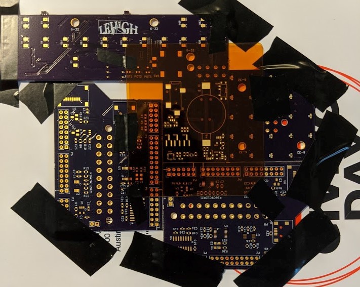
The results are... rather poor. There are quite a few pads bridged together, particularly at the QFN footprint & some of the sot23-5 footprints. I believe this happened because a few reasons: I used a floppy stencil. The jig-of-boards wasn't on a very flat surface and thus allowed for some wiggle of the target board. Lastly, I was greedy with my solder paste and only applied very small amounts in localized areas which meant I had to do several spreading passes to get full coverage. Applying a large amount of excess paste to allow for a single spreading action to get full coverage is a much better technique. In any case, these problem areas were pretty easy to fix with a pair of tweezers.
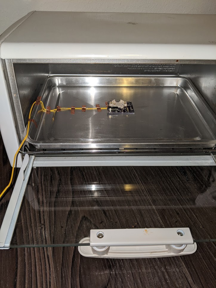
After then placing all of the parts, I reflowed the board in a second-hand toaster oven. Apparently you don't need to follow the exactly specified reflow temperature vs time curve to get decent results. Instead, you can just monitor the board's temperature with a thermocouple and just turn off the oven after reaching the peak temperature specified in the reflow curve.
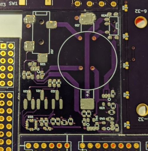
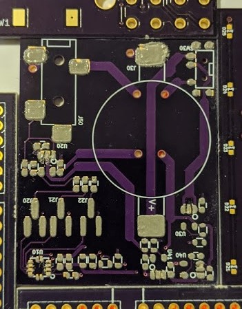
The bake went pretty well... except for that accelerometer! You can see that it's rotated about 30 degrees and that the QFN pads don't align! To fix this, I used a hot air gun to reflow that whole corner of the board and fix. A nicer hot-air gun specifically for doing hot-air reworks, like the ones that Hako makes, would have been much nicer to use. I'm surprised I didn't end up sending all of the nearby passives flying, but this worked out pretty well anyway.
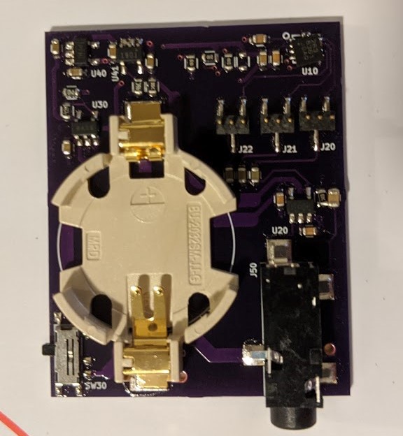

The astute will notice that, in my final assembly picture above, the TLV9001 has mysteriously grown 6th lead. After much head scratching and re-consulting of the datasheet, I realized that I had purchased the wrong part. I had designed for the "TLV9001 DBV" which I assumed was the only part that came in the sot23-5 package. In fact I had accidentally purchased the "TLV9001U DBV" because the right part is out of stock at Digikey. To solve this, I ordered a few "TLV9001S DBV"s since, besides the extra enable pin, it has the same pinout as what I needed for my design. Conveniently the enable pin is next to the positive rail pin, so keeping the part on by hand-soldering a bridge between the two pins was pretty easy. I also employed my favorite rework trick: stacking SMT passives on top of each other. I realized that my summing amplifier applies a |gain| of 1 to each channel. When all 3 channels are summed, there is a chance I can get a peak value of triple the peak of one signal and get a saturated output. So, stacking 3 10Ks in parallel on the feedback resistor pads was an easy way to bring the pass band |gain| down to (1/3) for each channel.
As expected, powering the device from the mic bias did not work. With battery power though, all components operate as expected. After mounting the board to the back of my uke with some electrical tape, I made a quick recording in Audacity.
This signal is pretty distorted because of saturation at the input of the audio codec. After adjusting the recording levels, I was able to record something that sounds a little better.
Unfortunately, there's quite a bit of noise, but I'm happy that it doesn't sound super awful. For now I want to play around with the jumper settings and analyze the differences between the waveforms of the three channels. Then, for a next design, I'd like to properly tackle the mic-bias powering, reduce the form factor (that battery is huuuge), and do a more robust noise analysis/characterization.
Discussions
Become a Hackaday.io Member
Create an account to leave a comment. Already have an account? Log In.