 jaromir.sukuba
Designing something from existing parts is not as trivial process as it may look. Unlike traditional design, where I start by selecting components I needwhere I identify the main components dictated by important features of things to be designed and then fill the gaps with components exactly as I need, designing from existing parts doesn't have the flexibility of finding exactly the needed component. I can select the main building blocks, but there are chances I will not find the small stuff to fill the gaps seamlessly, so I either have to live with suboptimal design or take a step back a change components I selected previously. That is, designing on the run.
What proved to be good approach when designing from existing parts is shotgun approach - collect as much parts as possible, put it on the table and try to mix and match to complete the puzzle.
For this project, I started with rough sketch of what I'm going to do
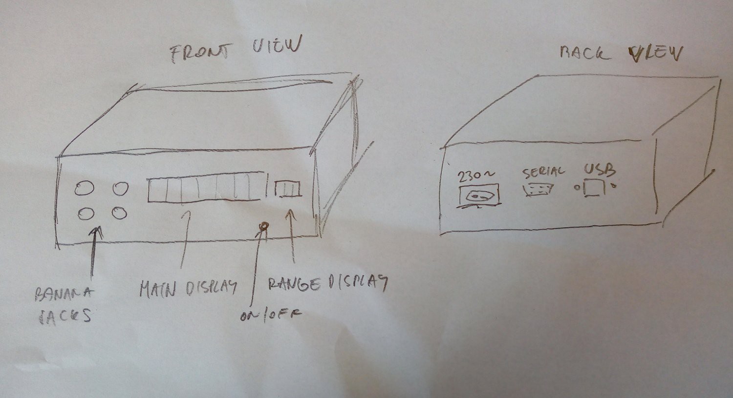
It may look trivial, but it's important step to realize what I'm going to search for first. Enclosure is obviously the most important and defining component of whole design. I estimated the size of device to be roughly of A4 paper size footprint, with height something like 5-10cm. For those sizes, printing the enclosure with 3D printer would be slow and painful, since my printer is both glacially slow and has small-ish print size, so I'd have to glue the enclosure from a few parts. That lead me to decision to use off-the-shelf enclosure.
Fortunately, I have a few enclosures in my junkbox and there is one that fits the bill quite well - CP-15-34 I bought a few years ago for a project that never got to reality. I bought it from TME but now it seems unavailable.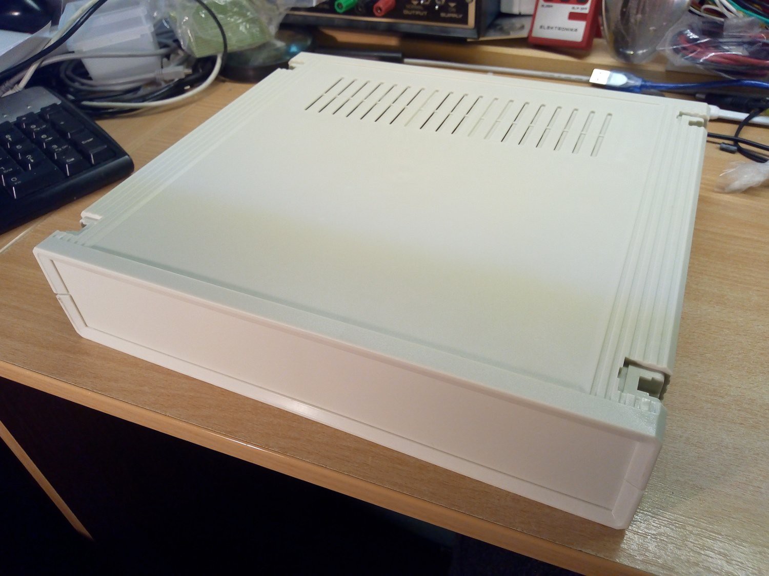
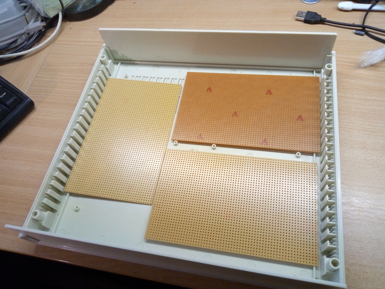
I estimated the PCB real estate to roughly three PCBs of 10x16 size. One for power supply, one for analog electronics and one for digital portion of device. Quick check revealed there should be enough room to fit them
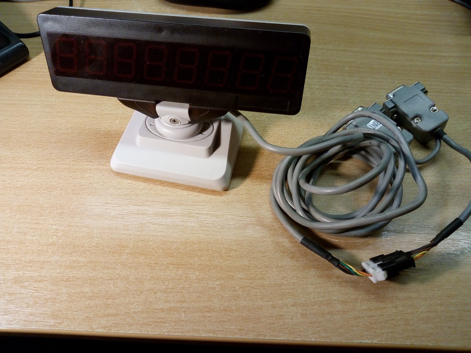
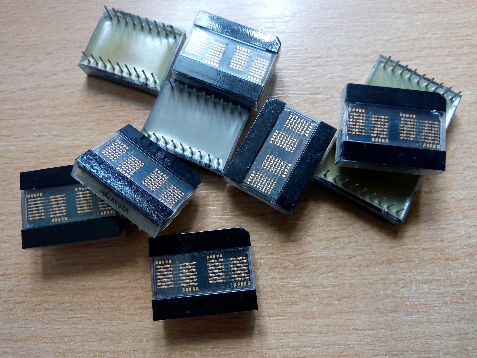
Since the enclosure is 7cm in height, in worst case I'd need some additional circuitry, I could stack two PCBs. I felt like the next deciding factor would be front panel displays. I took a deep grab in my junkbox and found - among others - this old display unit from cash register. I bought this on a local flee market uhm... 10 years ago or so.
After removing a few screws I cracked the enclosure apart to find familiar IC - MAX7219
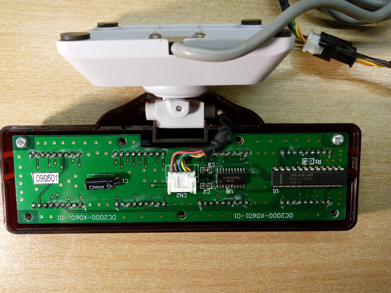
Oh my, that looks good. Now take out whole package.
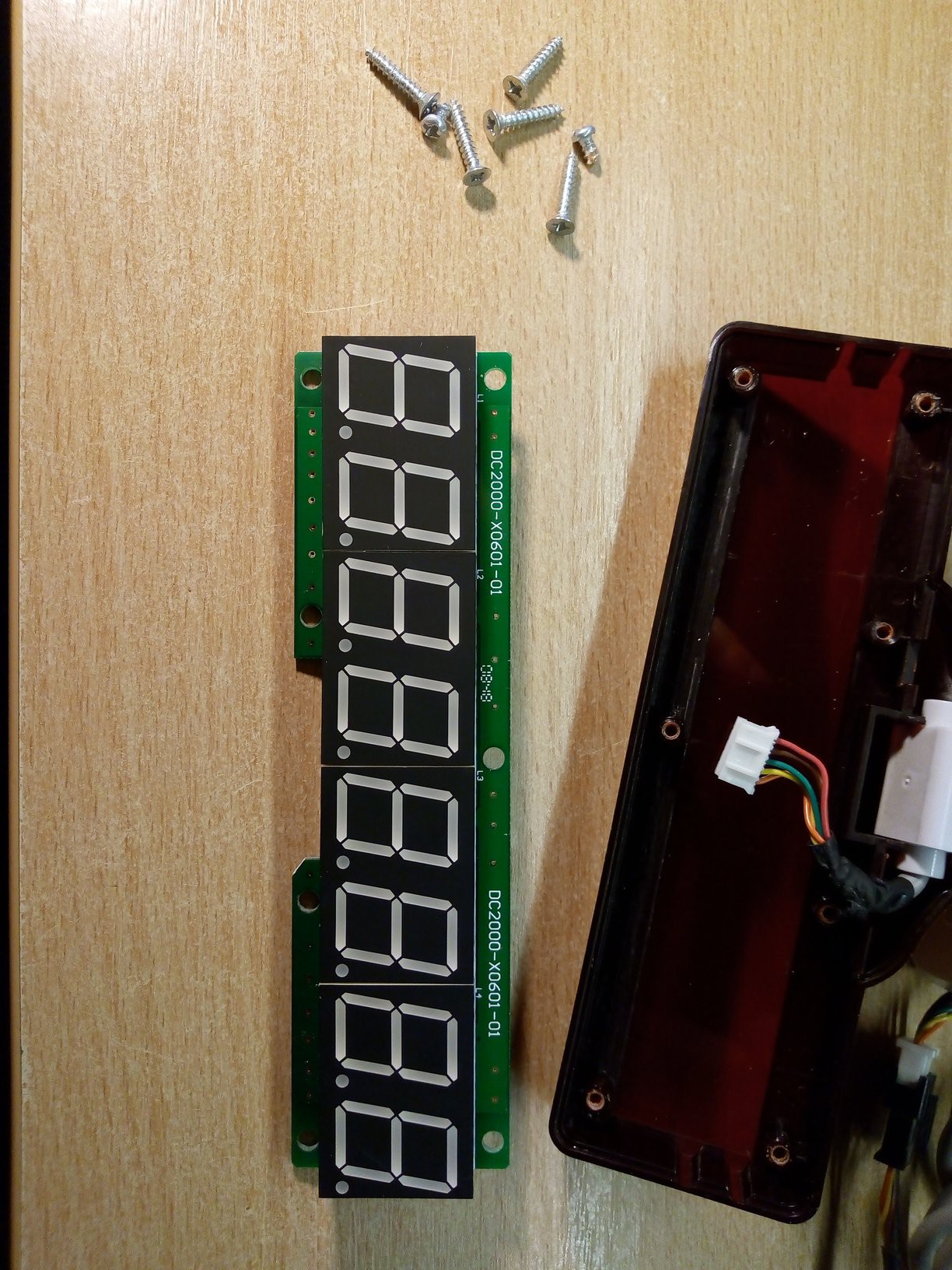
Great 20mm height LED displays. After a quick reverse engineering job I made this literal back-of-the-envelope sketch capturing cable pinout.
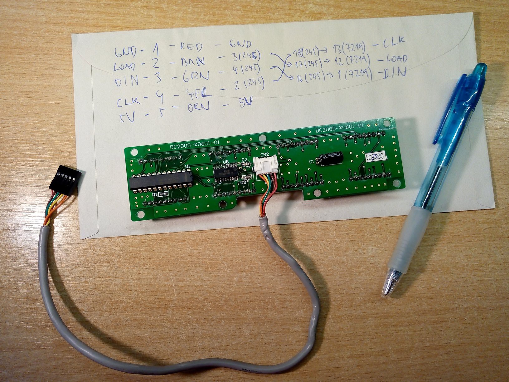
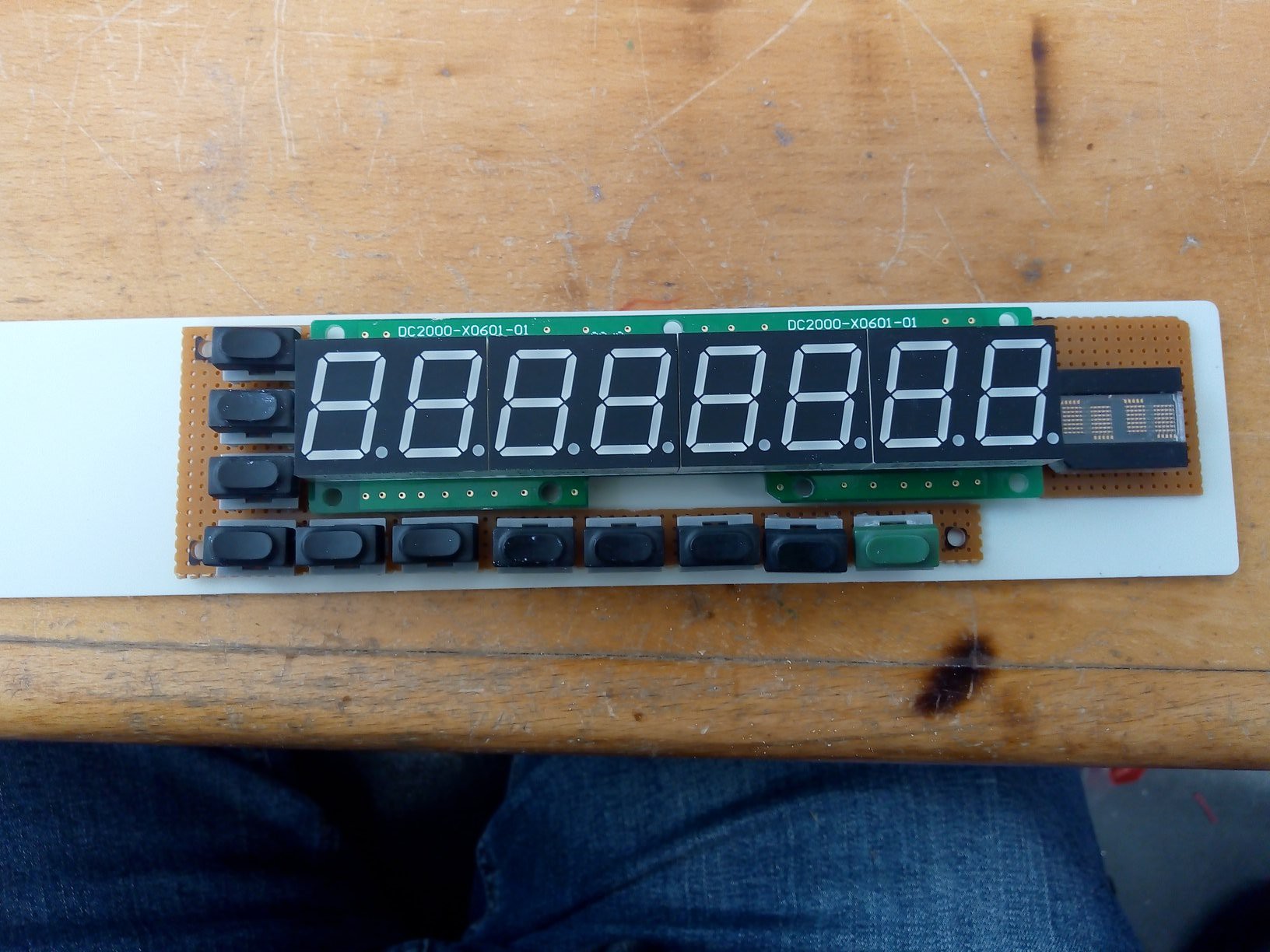
And another few moments later I had the display working with my random microcontroller test board I had around.
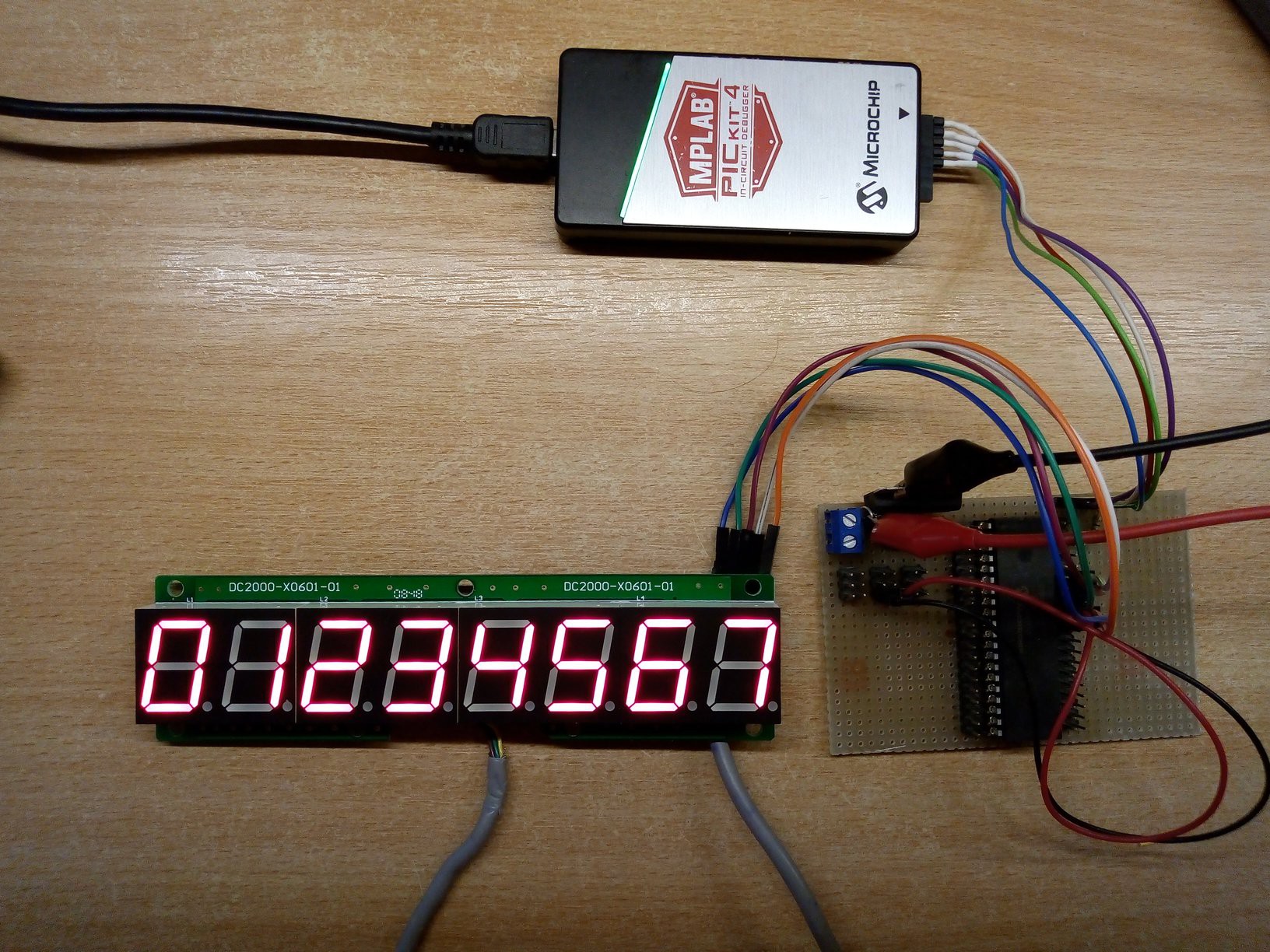
Fantastic! Now I can continue with parts identification.
For the smaller display (displaying measurement range) I opted for HDLO-2416, because I had a few of them from teardowns of industrial temperature controllers. This part is something like 25 years old, but still manufactured!
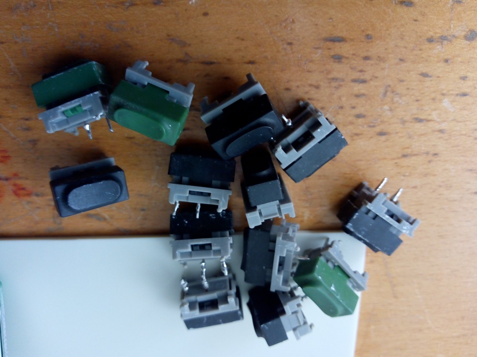
Now I realized I need also keypad on the front panel, so I can select measurement function and range. I always liked the Marquardt 6450 series switches, since I salvaged them from sewing machine controller years ago. Those are the historical ones from sewing machine made in 80's, containing goldmine of vintage parts.
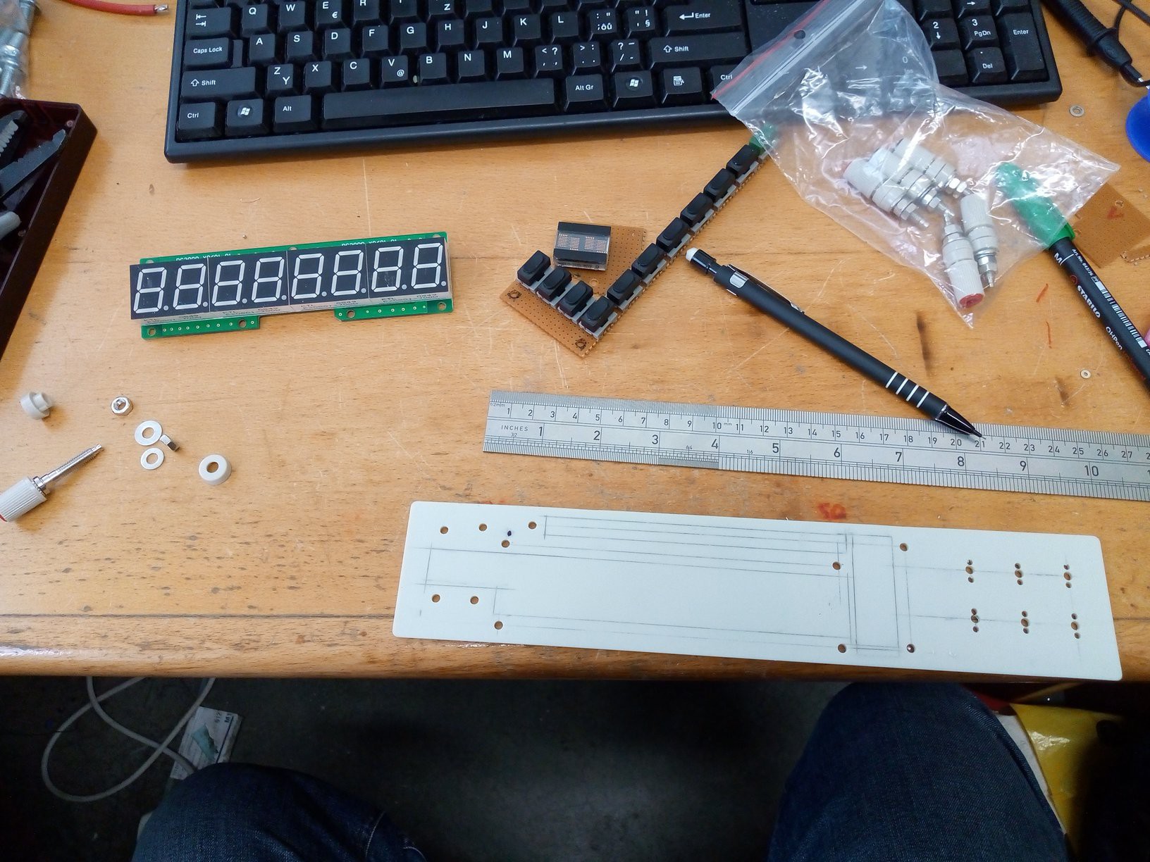
For starters, I cut two appropriate pieces of perfboard for keys and small display and laid out on enclosure front panel.
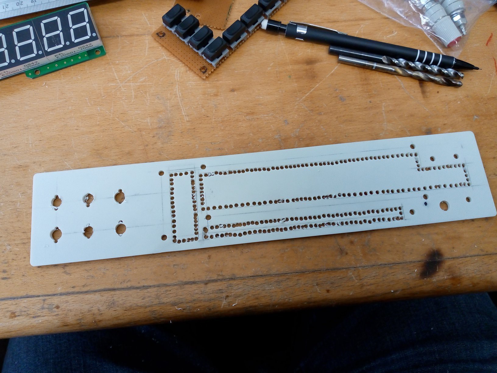
Looks like a tight fit, but should be doable. So now, he main parts of front panel are identified, I can proceed on by drilling a few holes.
A few more holes
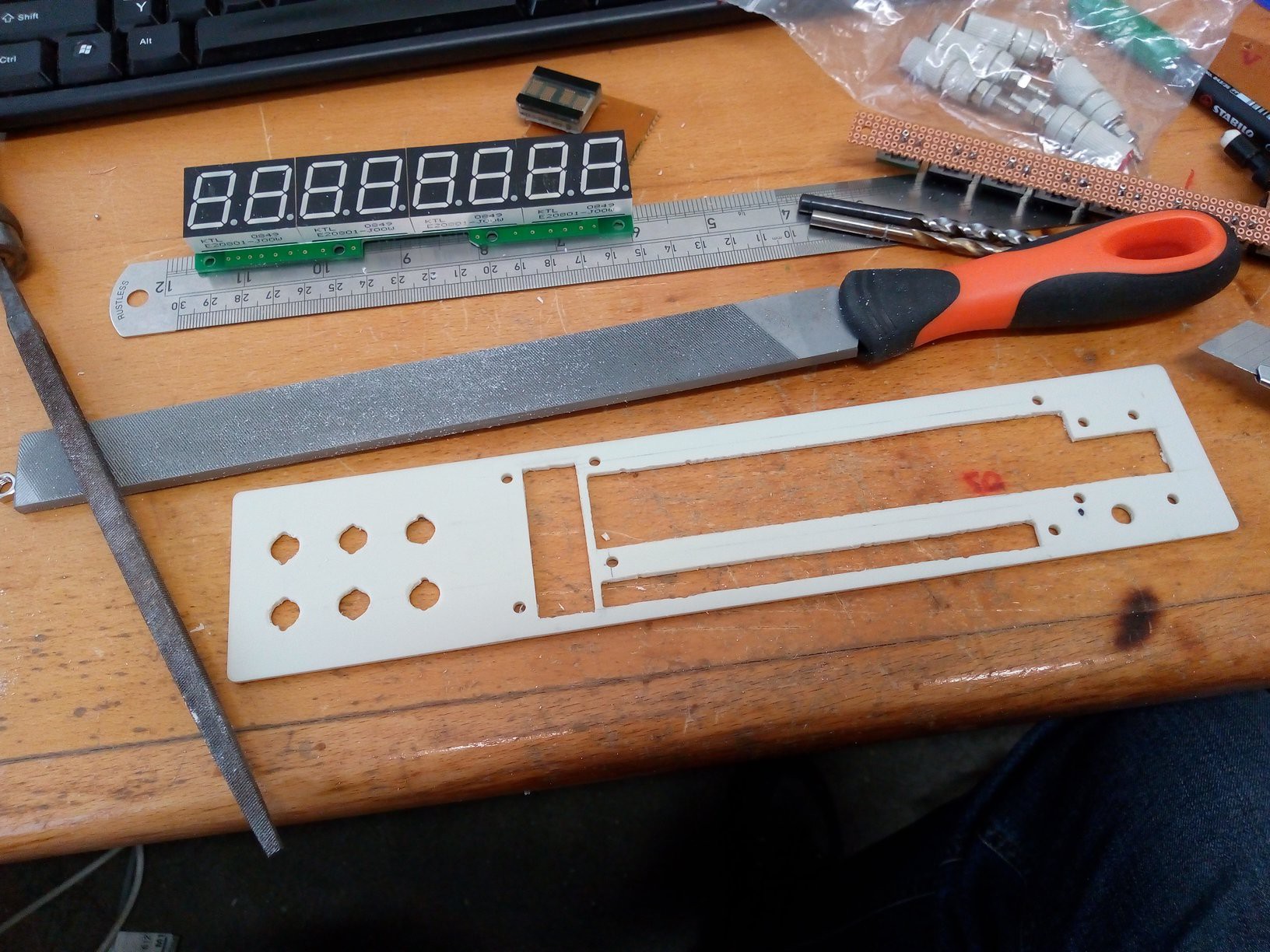
Cutting a few bits of plastic
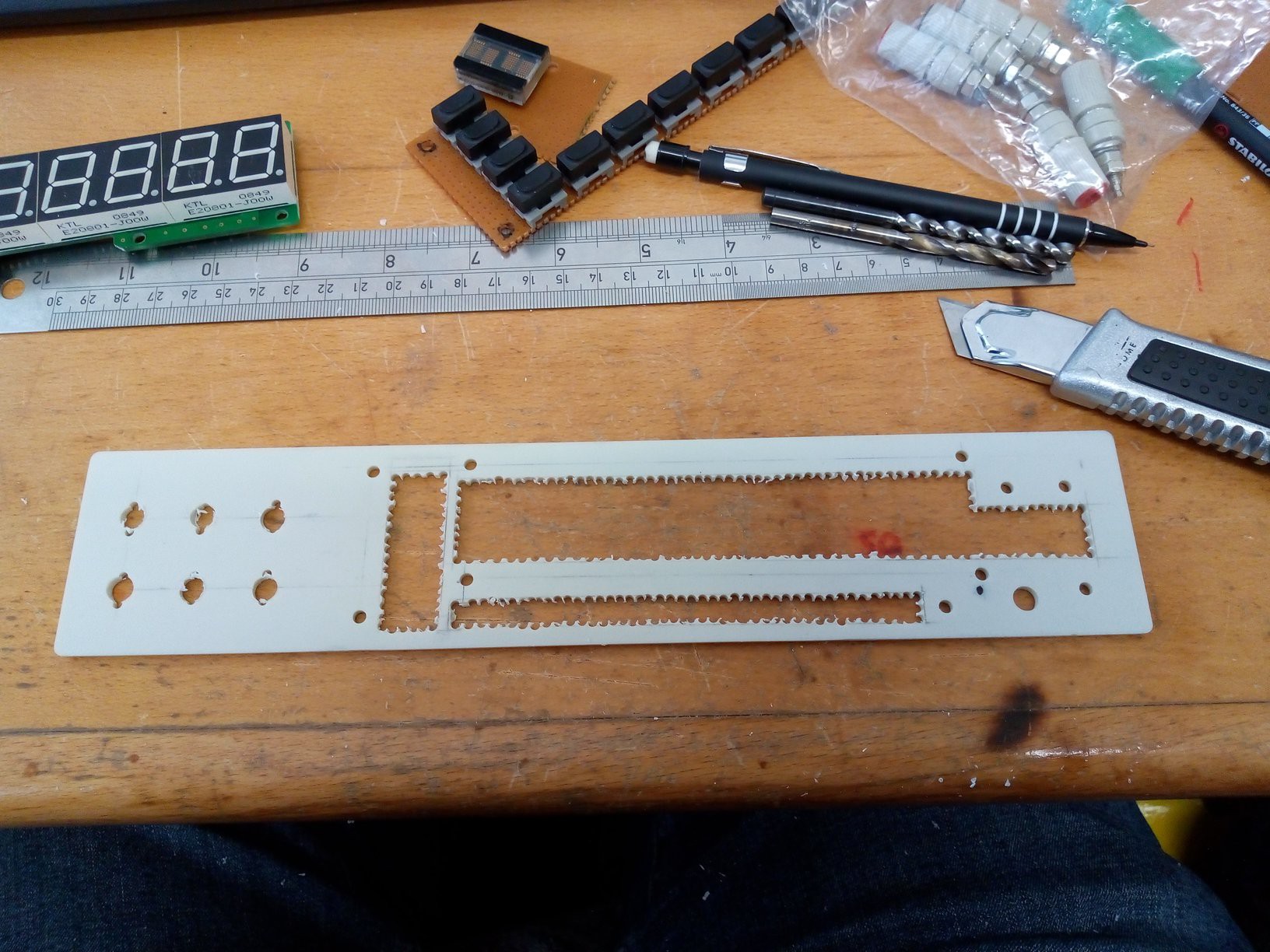
Working out details
Aaand it fits!
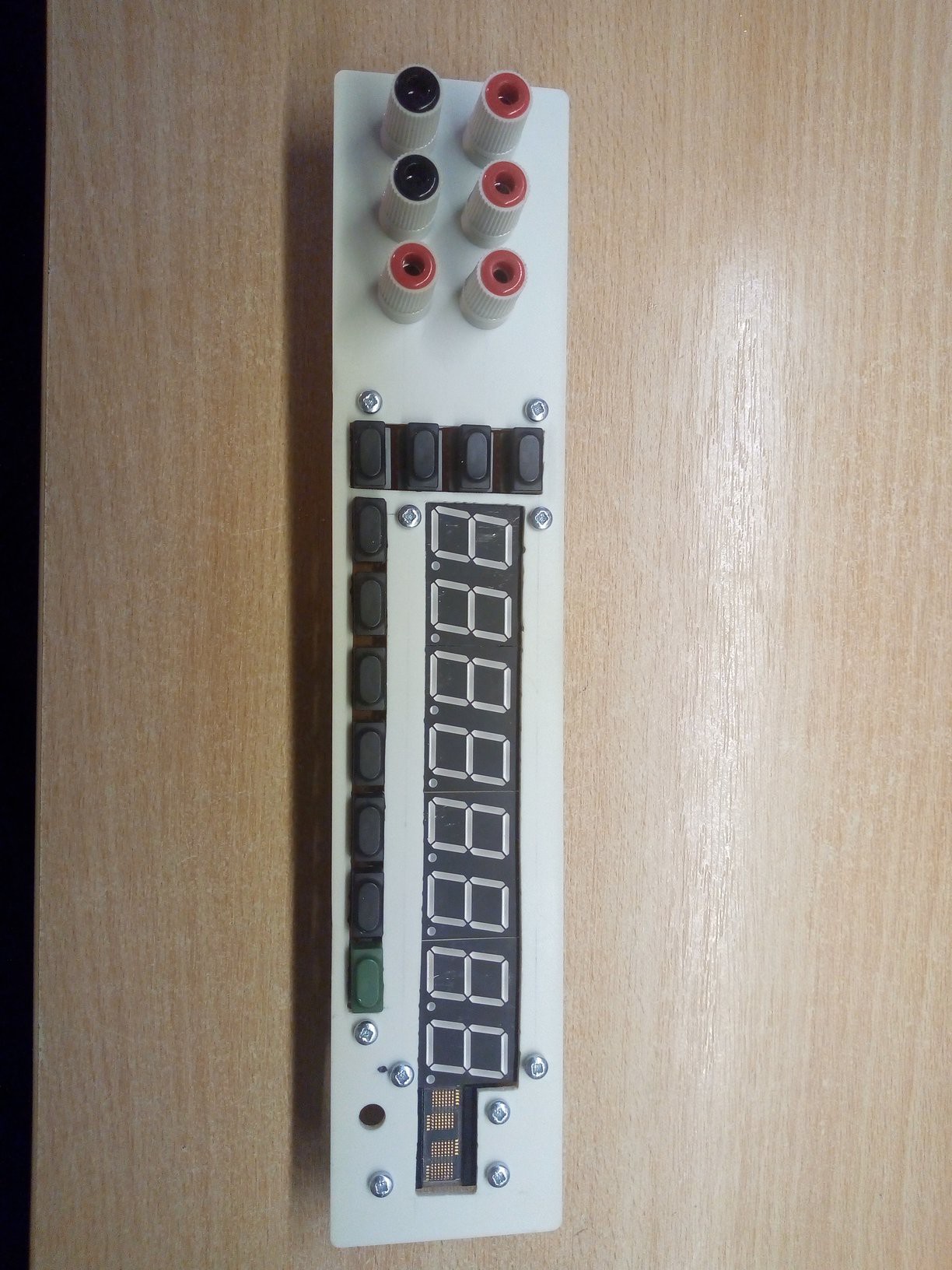
Looks fine from back, too.
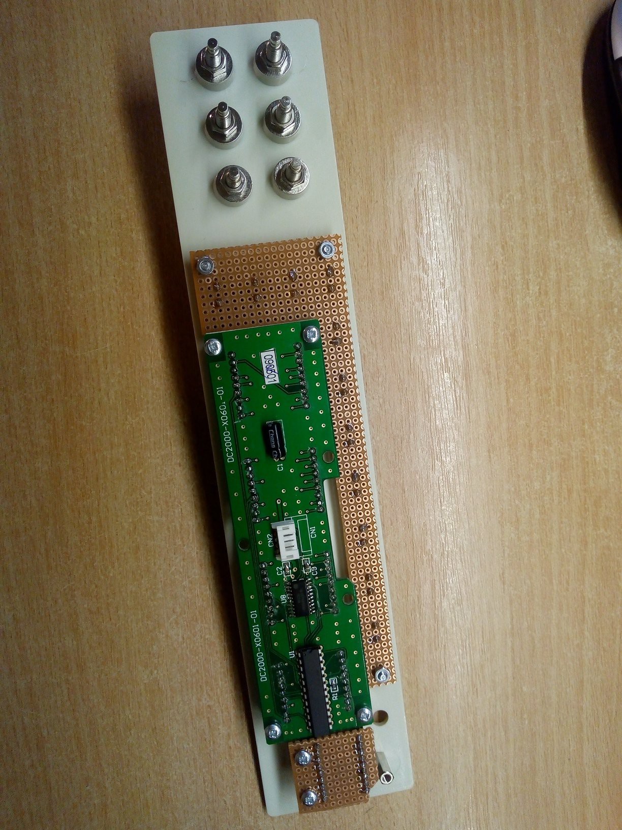
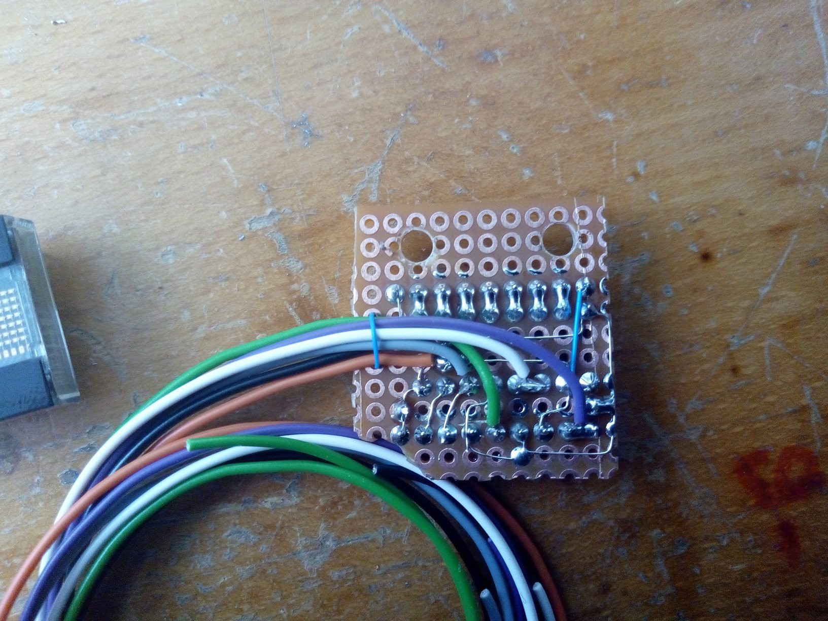
When everything fits nice mechanically, it's time to make some electronic works. Since there is 11 keys on front panel and HDLO2416 has something like 10 control lines, I wasn't much keen on having such as many wires coming to front panel, I opted for I2C expander PCF8574 for keypad and 74HC595 for the display, to reduce needed pin- and wire-count.
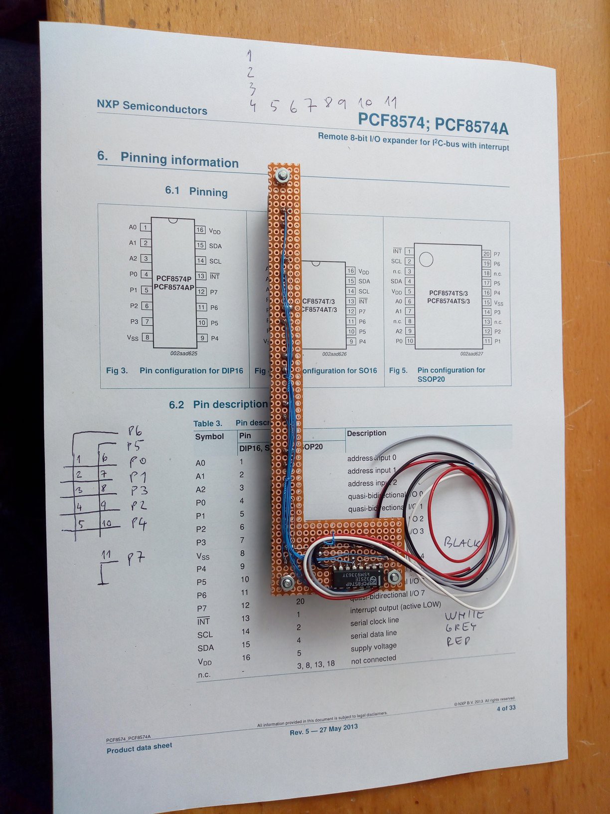
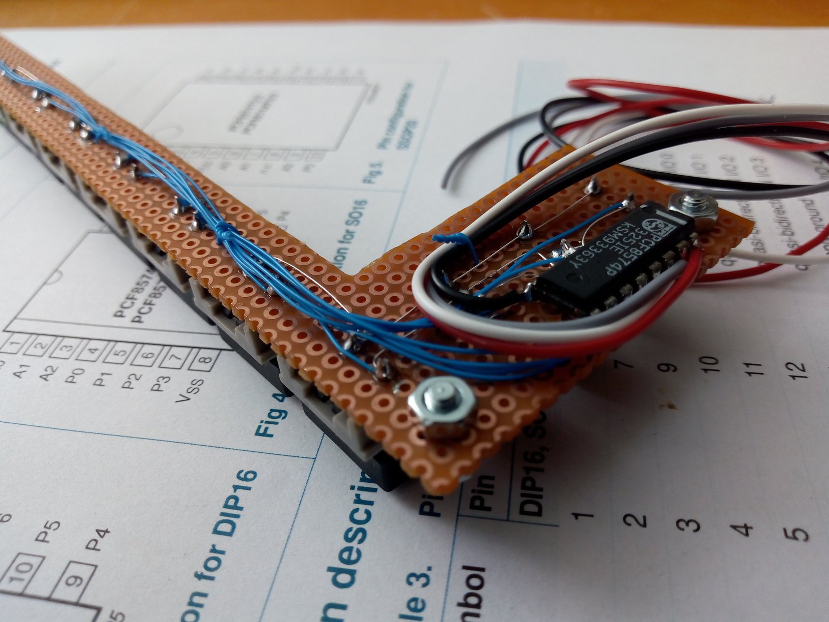
I printed out the PCF8574 pinout and used that paper as helper for wiring the board, as well as "notebook" to keep reference of what I actually wired. At the time I had no other schematics or resources, it was just impromptu work.
The same goes for HDLO display
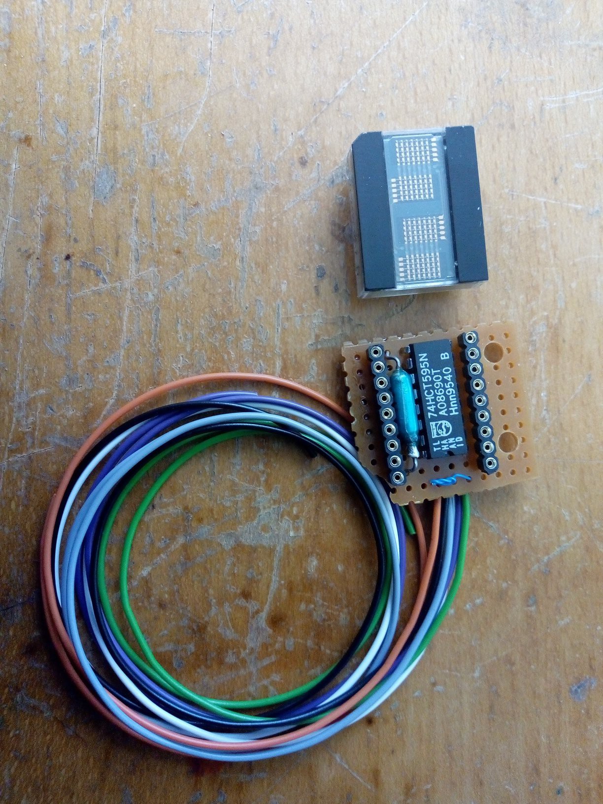
All my documentation is a few notes on 74HC595 datasheet page and those pictures. That being said, I plan to redraw it all into usable form.
So, front panel populated and wired, in next project log we will take a look at big PCBs in the device.
Discussions
Become a Hackaday.io Member
Create an account to leave a comment. Already have an account? Log In.