 jaromir.sukuba
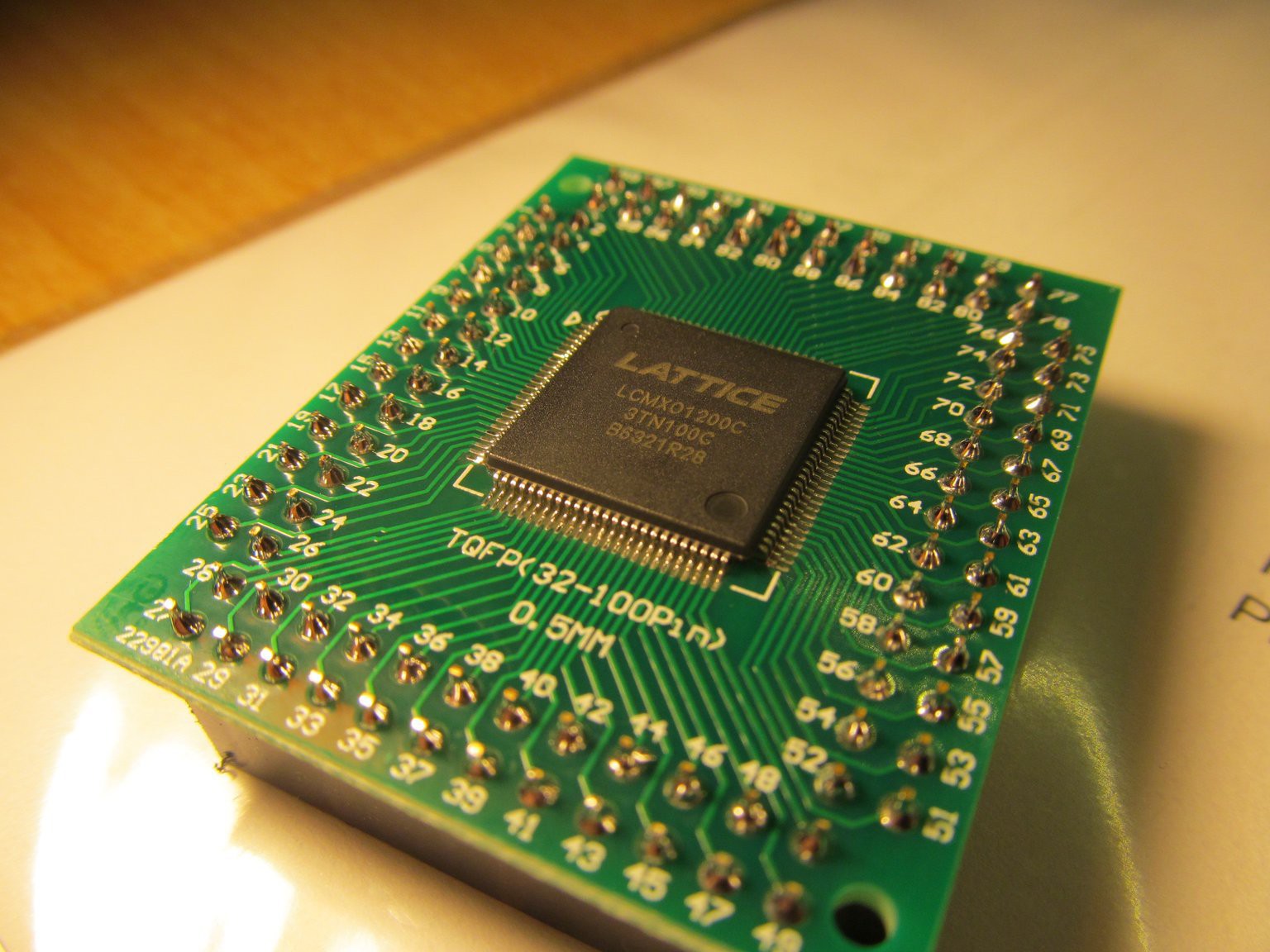
Heart of the ADC will beat inside FPGA, driving all control signals of ADC. I opted for Mach-XO part from Lattice. This part is linked to my mistake in order from Mouser for a particular order few years ago - I wanted MachXO2-1200, but by my mistake I ordered MachXO-1200. After a bit of teeth grinding I ordered the correct parts in second purchase and was left with two parts I had no other use for. Being older MachXo family, it has higher current consumption and totally different pinout than XO2 part. But now it got chance to rise from my junkbox and shine. Soldering to breakout board
Oh and I also printed this pinout. There is no such as pinout in FPGA datasheet, so I composed it from csv pinout file provided by Lattice.
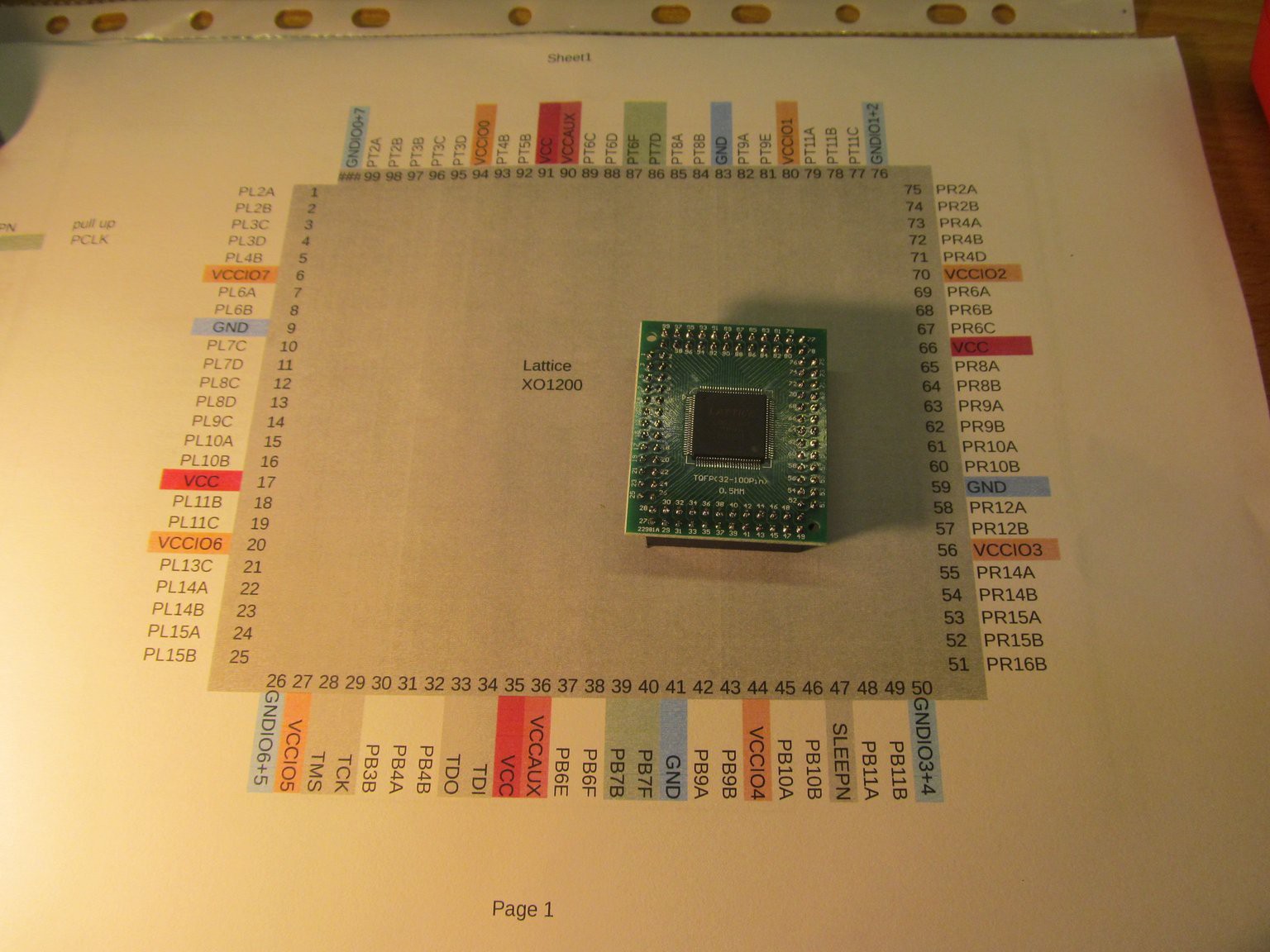
This thing serves as reference and design logbook during board design. Notice I had no clear schematics of resulting boards at the time of building the boards, just parts pinout prints adn a few ideas in head.
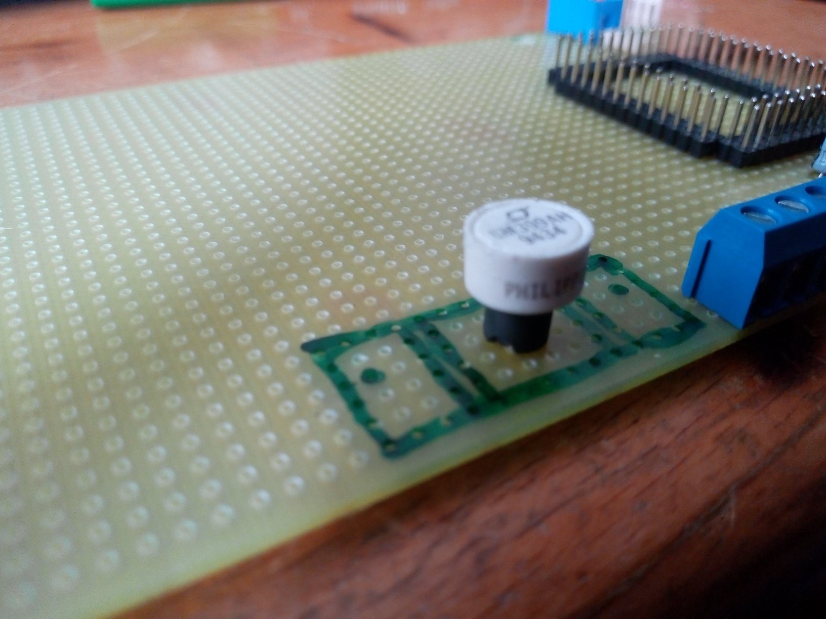
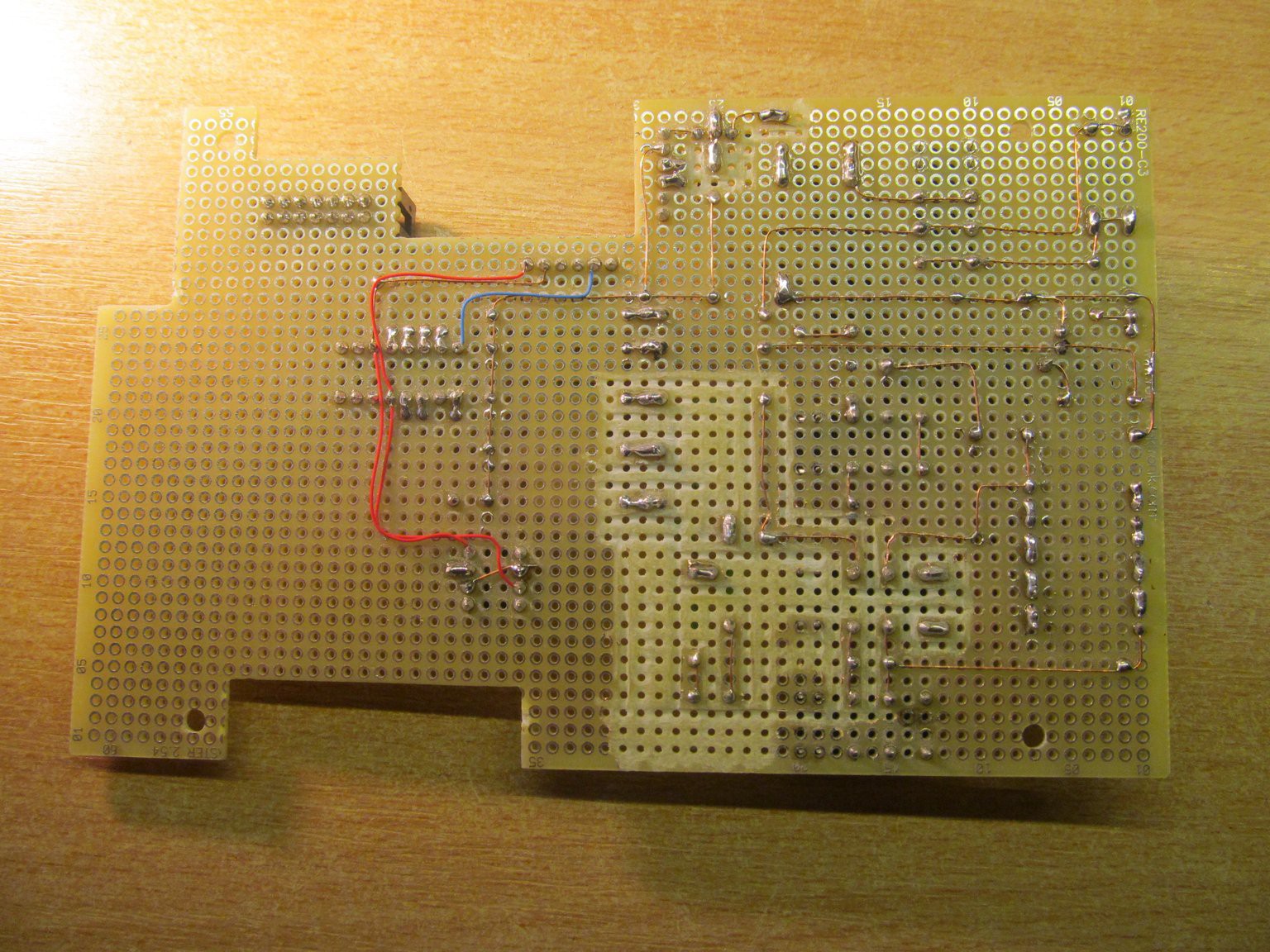
I started with one of most important parts of ADC - voltage reference
Added a few more bits, many of them taken out of the boards in previous log
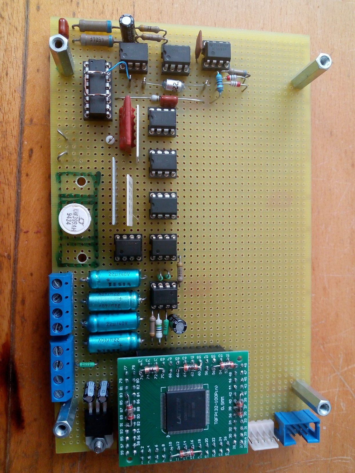
This alone is working ADC portion. Later I added voltage buffer/amplifier and did some preliminary tests
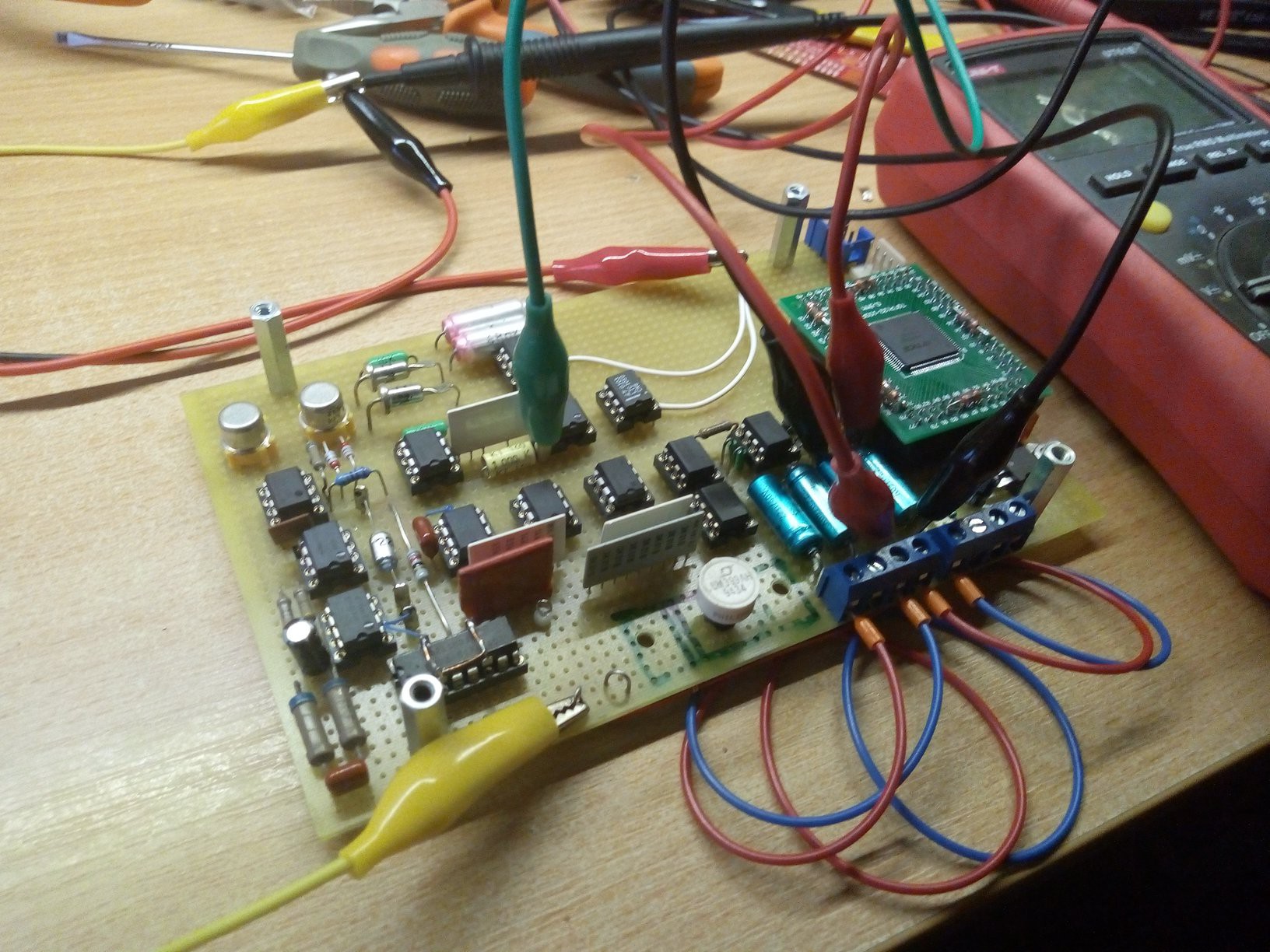
Then I entered the waters of digital world by soldering dsPIC30F6012A to the breakout board.
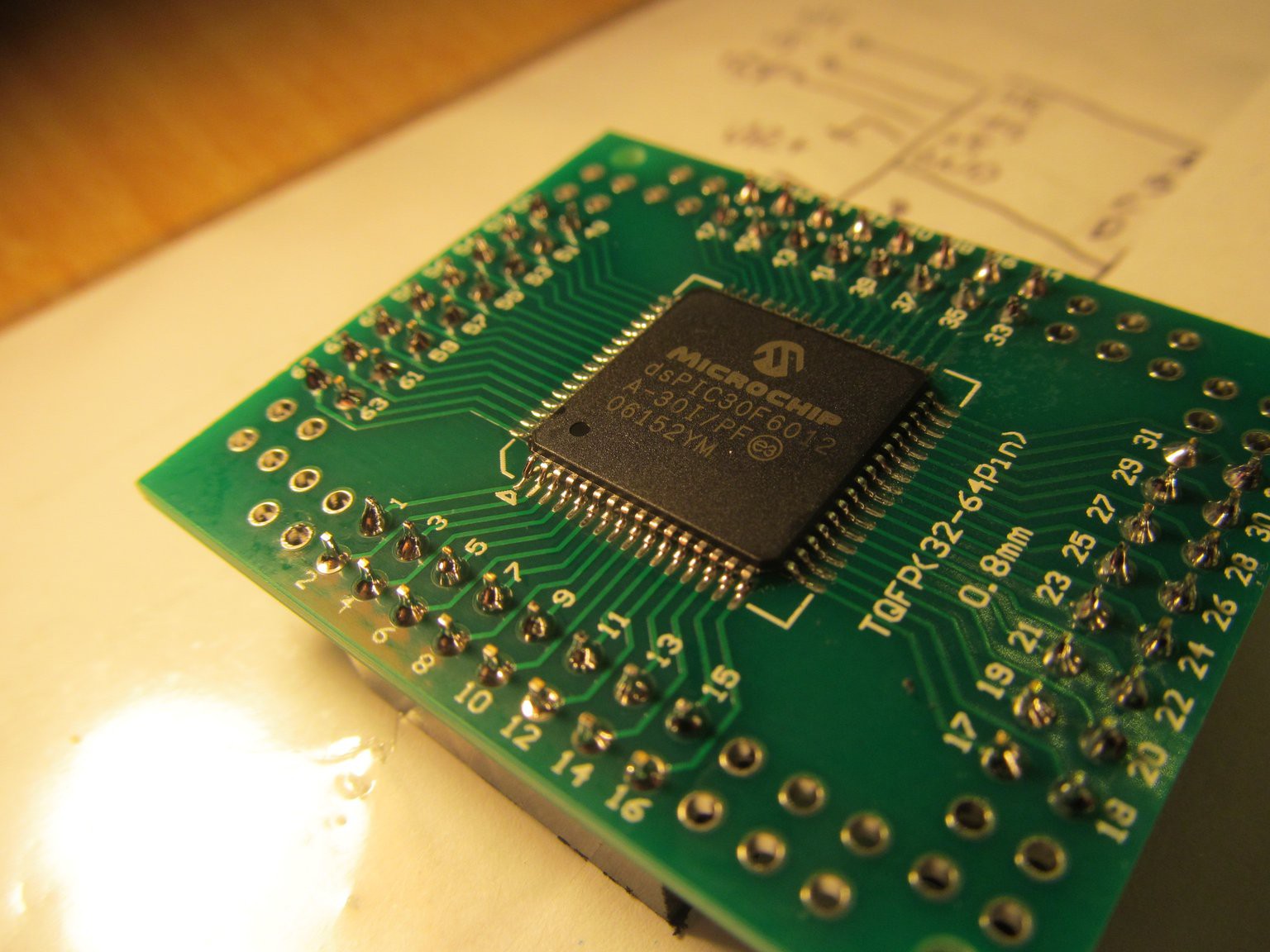
dsPIC30 is oldest family of Microchips 16-bit low-end DSPs, released in early 2000's. I still remember how stunned I was reading it's datasheet back in the day, when all my experience ended at PIC16F84. When I entered university, i was able to order a few Microchip samples at my university account and this beauty was one of them. Manufacturing date early 2005... Oh, time flies so fast. By today's account. the MCU isn't anything stellar, but will do the job here.
When coronavirus outbreak happened where I live, I stayed with my family for long weeks at home, occasionally doing health-trips to woods around here, with lots of fresh air and almost no humans. During this time I relived geocaching hobby.
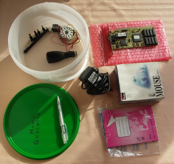
In one of caches - GC12N2M for anyone interested - with ham-radio theme I found 18,432MHz crystal.
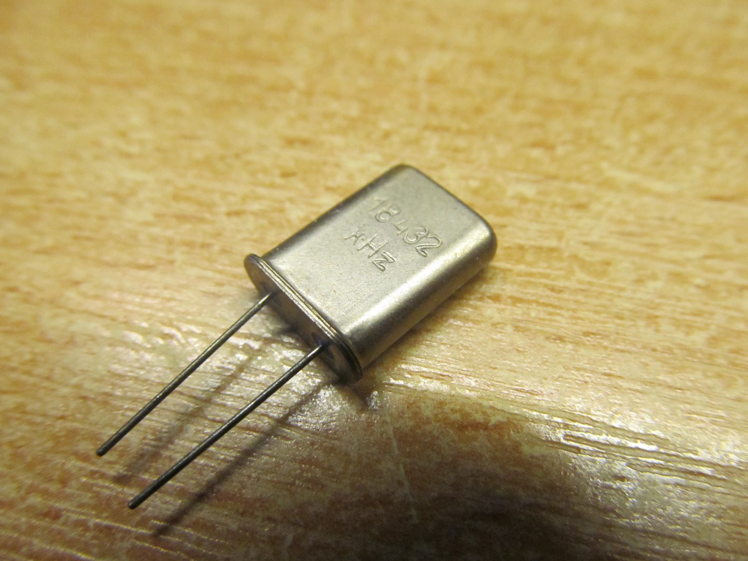
18,432MHz looks a bit strange, but I rang my bell immediately at the cache place - dividing the number by 160 gives 115200, common baud rate. It's good crystal for anything that has to communicate via serial port at standard speeds. By the way, this crystal was also made by TESLA and I'm pretty sure it's probably as old as I am. I wonder what was it's life before it got into my hands, but this one definitely was bartered from cache to my home.
PIC, crystal, optoisolator and a few miscellany parts on digital board, testing dispalys and keypad
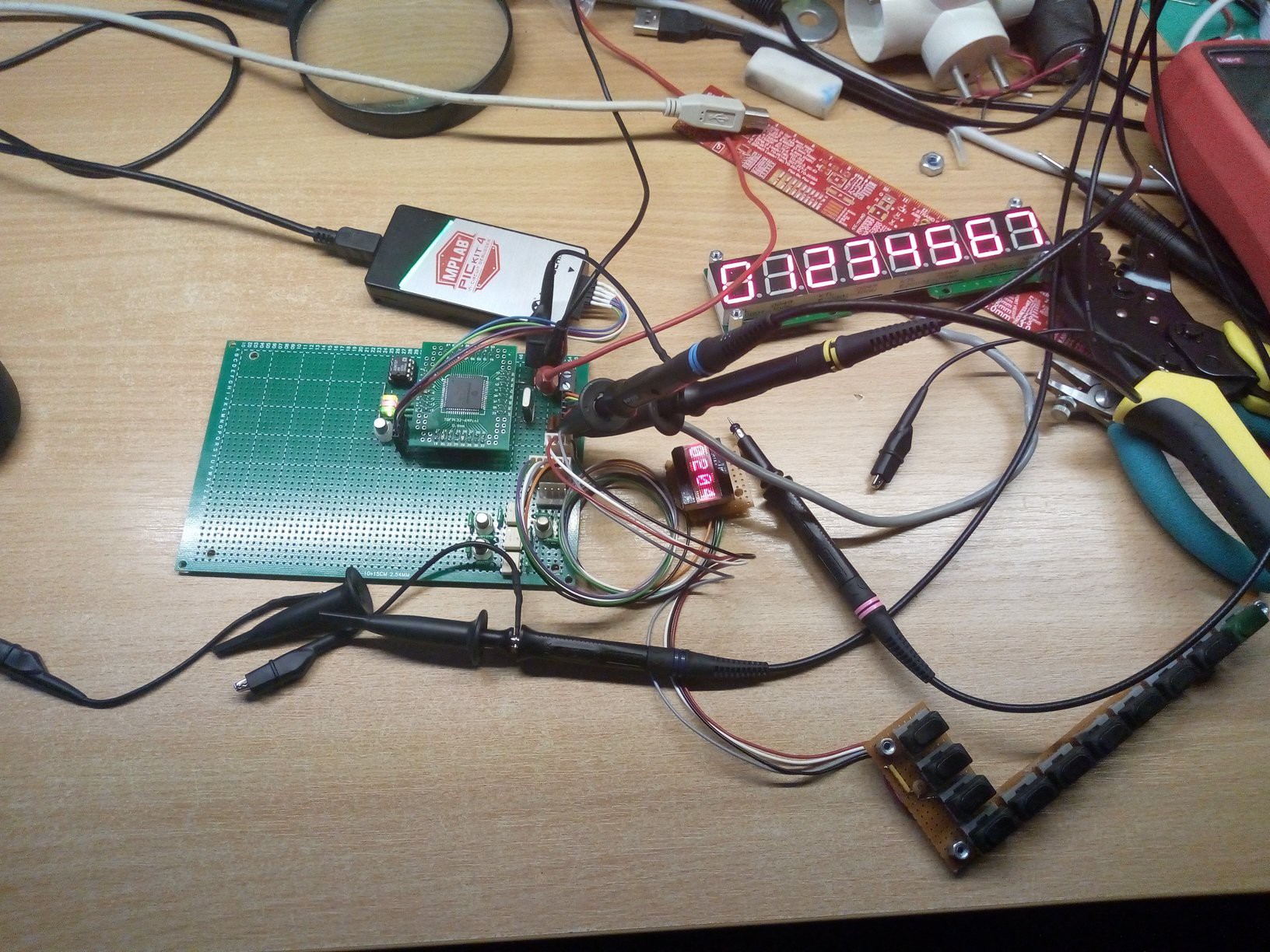
When basic testing was made, I connected bits together
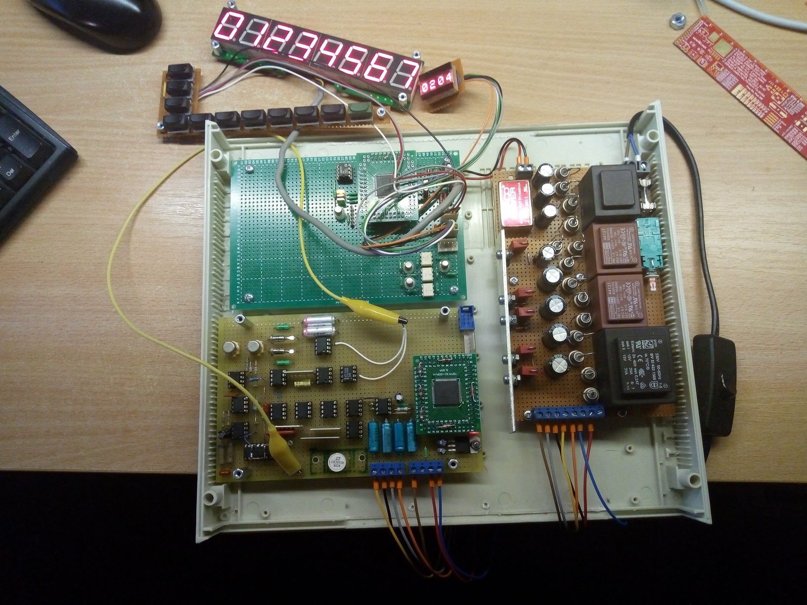
Notice the power cord - it's cut away from desk lamp that broke months ago. I cut the cord with in-line switch, as it's quite useful for testing out things. Later I added ohms current source to analog board and was practically done, as boards real estate conditions didn't allow much more to be added.
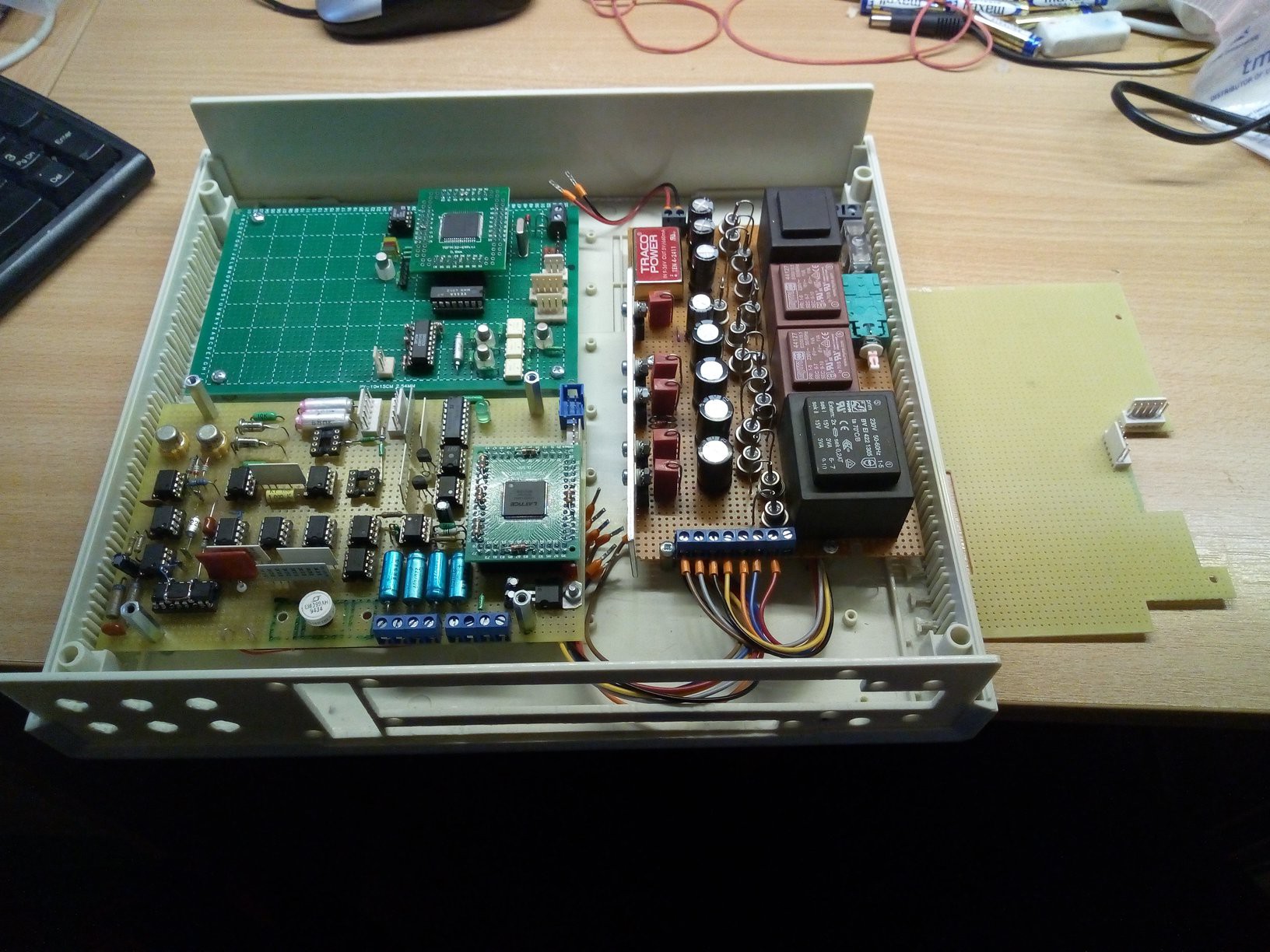
Notice the PCB on the right. Since there is just ADC and ohm current source on analog board, voltage dividers and current shunt are going to another board, carefully cut to fit cut-outs to connectors below, stacked on top of analog board.
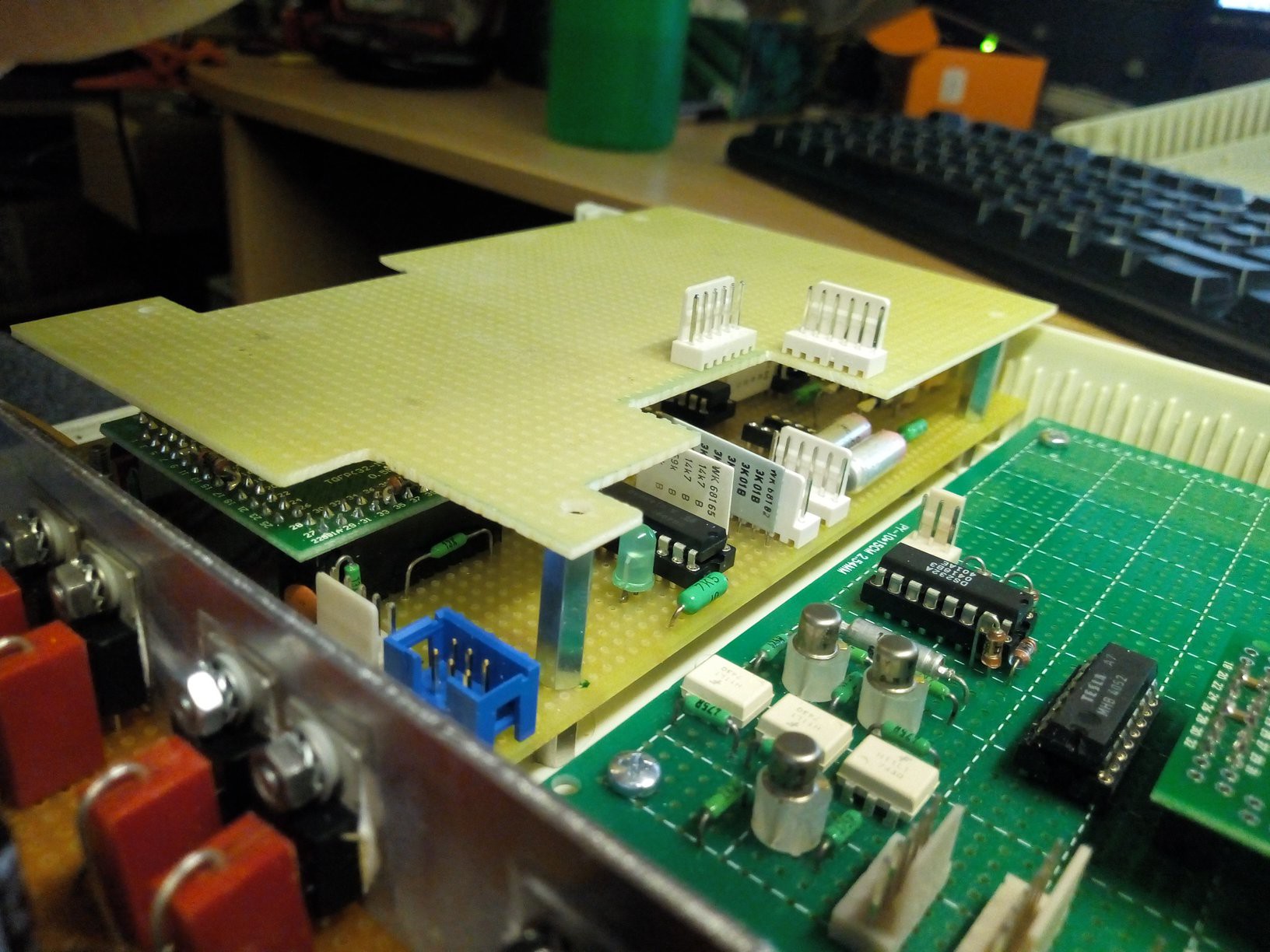
I proceeded with components soldering, as well as cutting out isolation barriers to decrease leakage and increase voltage strength.
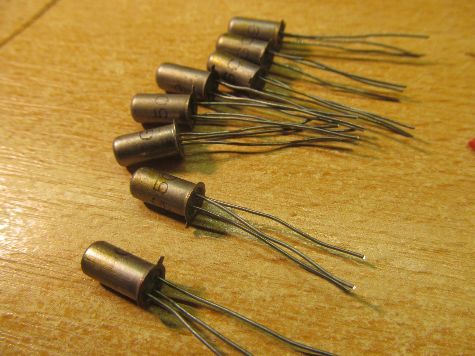
There are four bistable relays, controlling those is quite simple - two coils instead of one coil in your typical relay. Bring short pulse (~10ms) to one coil, relay switches and stays switched after pulse is gone. Pulse another coil and relay switches back. For this I needed 8 switches, comprising of NPN and PNP transistor (to convert from PGA 3V levels to 5V).
In my stash I found those eight PNP germanium transistors and I was totally decided to use them in here
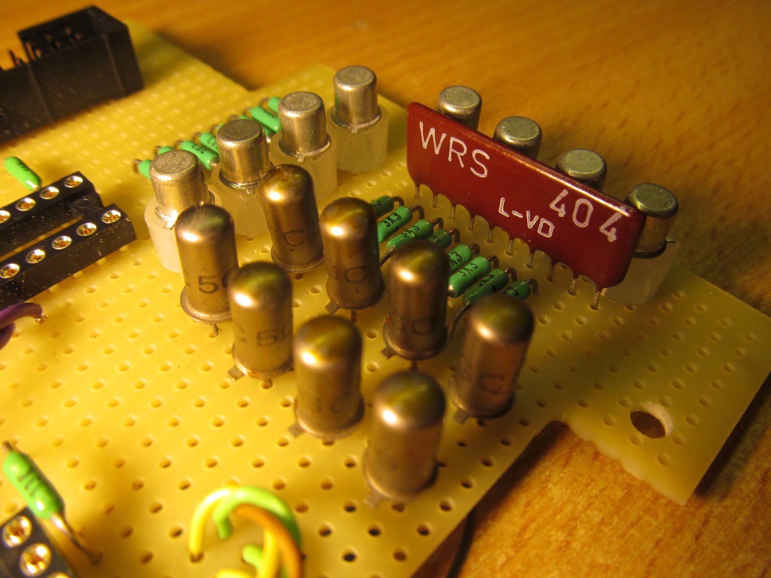
And here it is, along with 8 silicon NPN transistors and hybrid resistor network (but ordinary 3k3 SIL network would do the job as well)
Here is view of all four boards at the right place
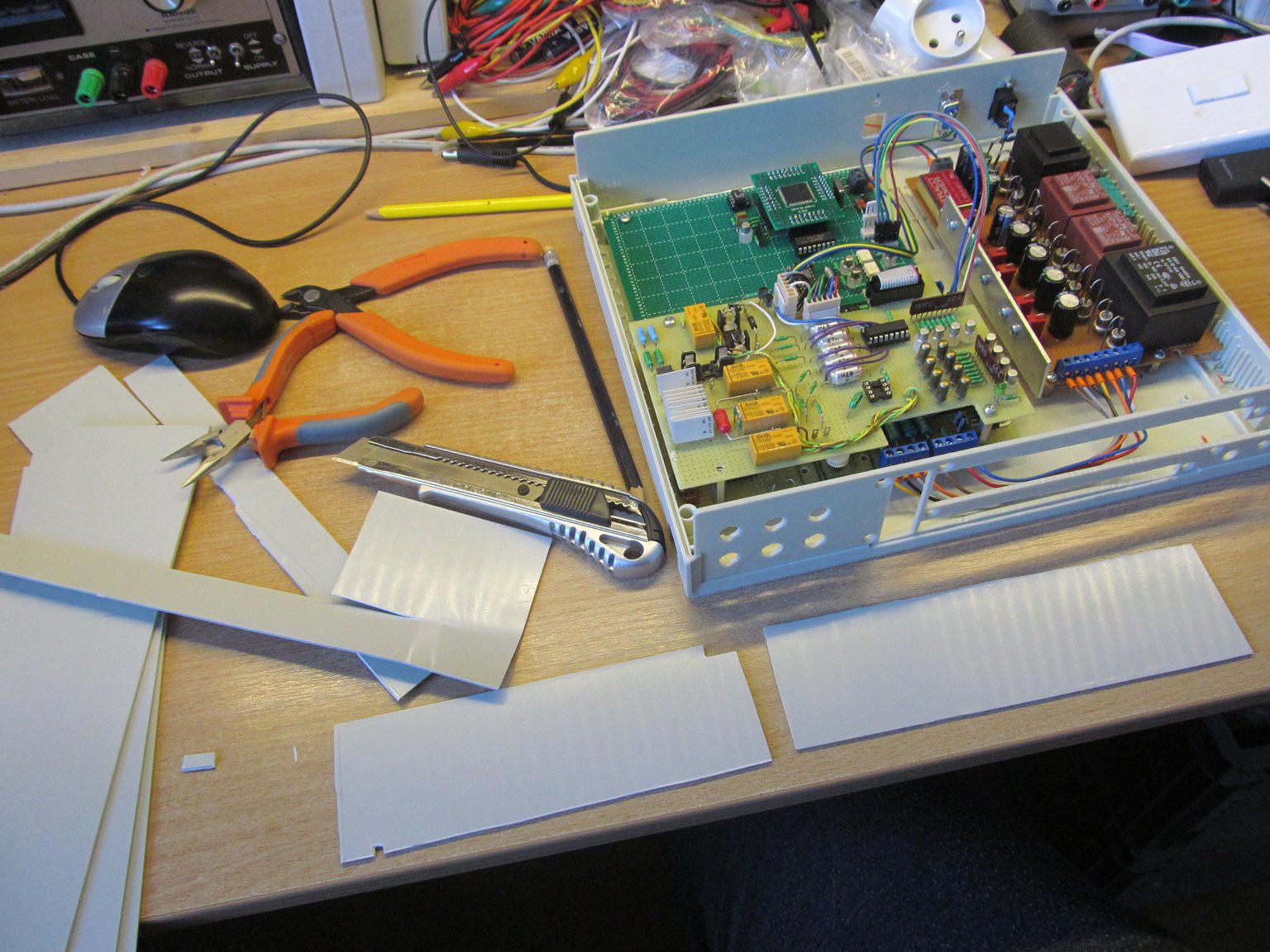
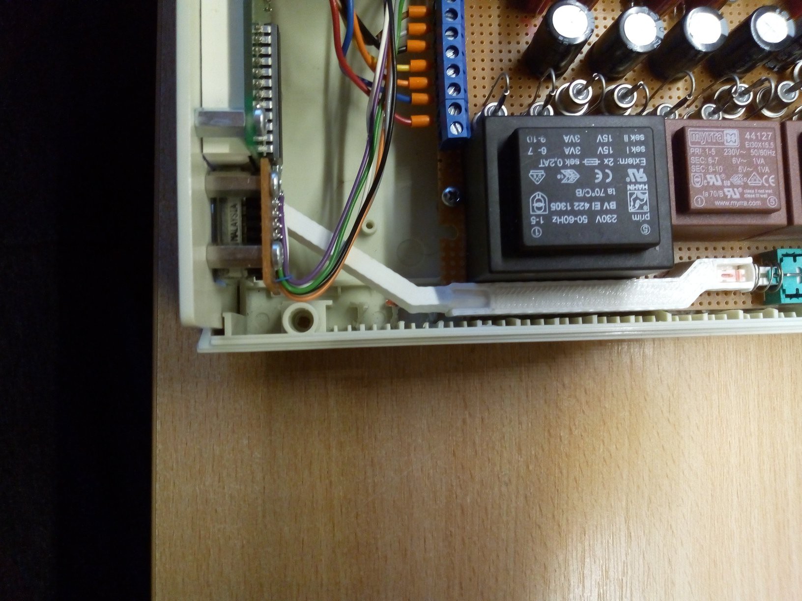
Notice the plastic cutouts - I cut those to separate the analog, digital and power supply parts. And here it is, glued to a place
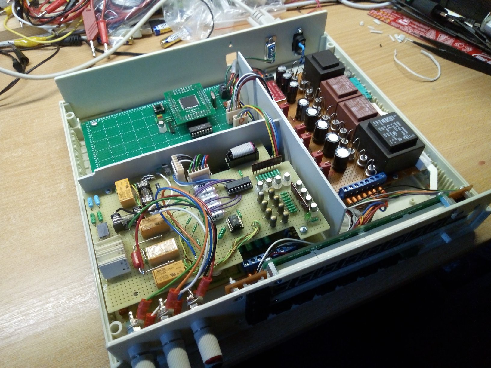
In the left part you can see plastic shaft I printed to transfer push action from front panel to push lever of PCB mounted switch
In the following log I'll try to wrap up this multimeter design.
Discussions
Become a Hackaday.io Member
Create an account to leave a comment. Already have an account? Log In.
That thing is a thing of beauty! I am totally amazed by your ability to come up with solutions to every problem with parts you have in your drawers, even if those are some really special parts I must admit :)
Are you sure? yes | no