0%
0%
Become a Hackaday.io member
Already have an account? Log in.
Just one more thing
To make the experience fit your profile, pick a username and tell us what interests you.
Pick an awesome username
hackaday.io/
Your profile's URL: hackaday.io/username. Max 25 alphanumeric characters.
Pick a few interests
Projects that share your interests
People that share your interests

 Rue Mohr
 José Júnior
 Yann Guidon / YGDES
 brandon
thanks for your interest!
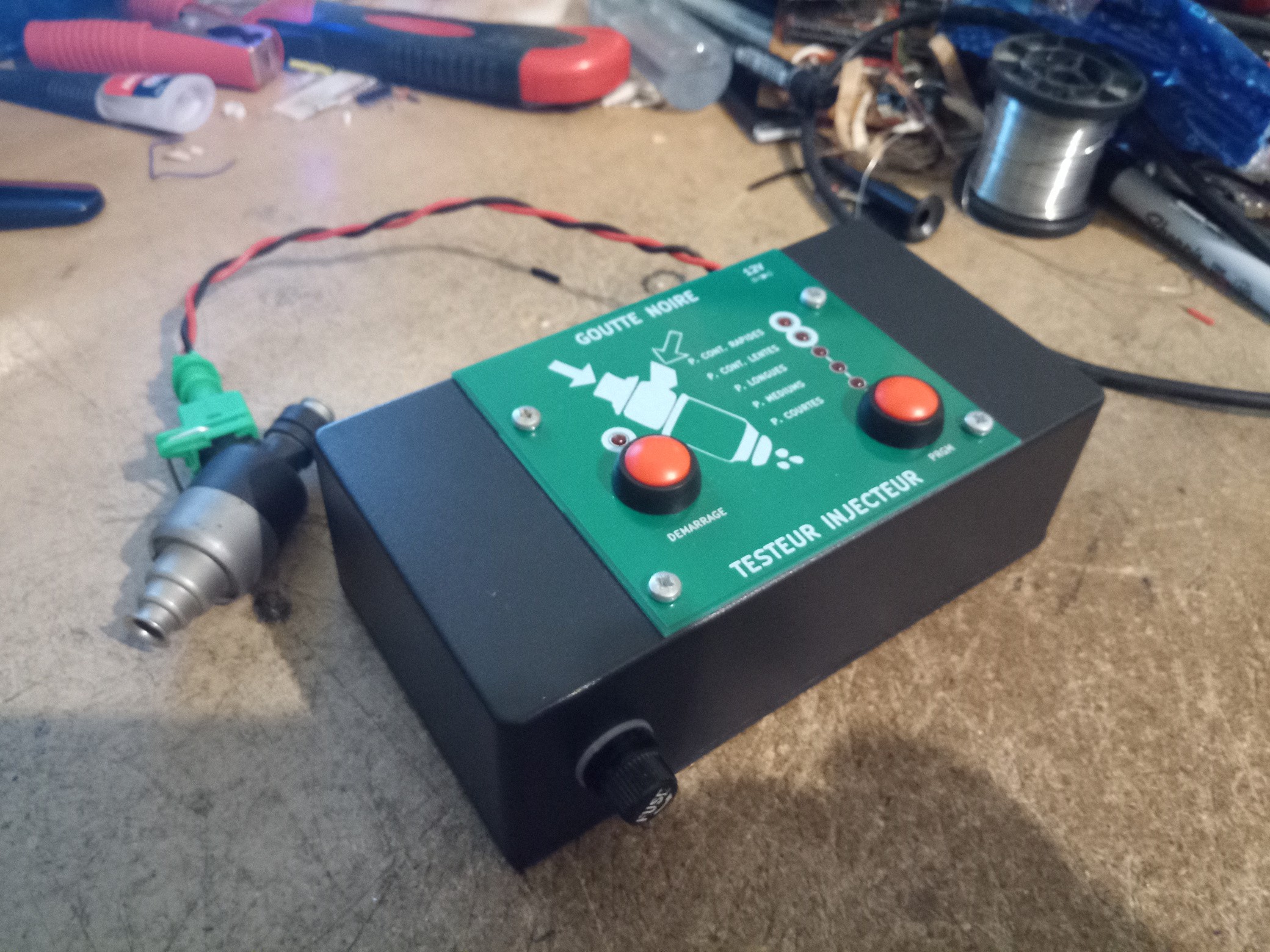
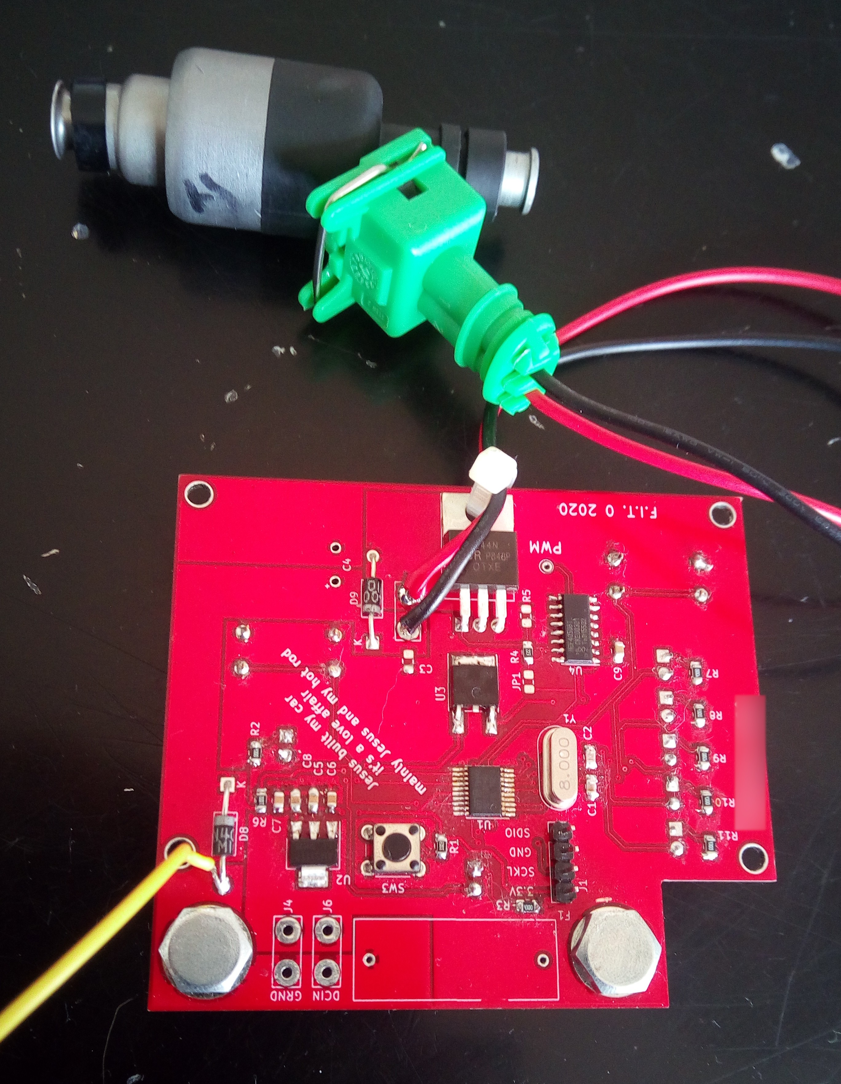
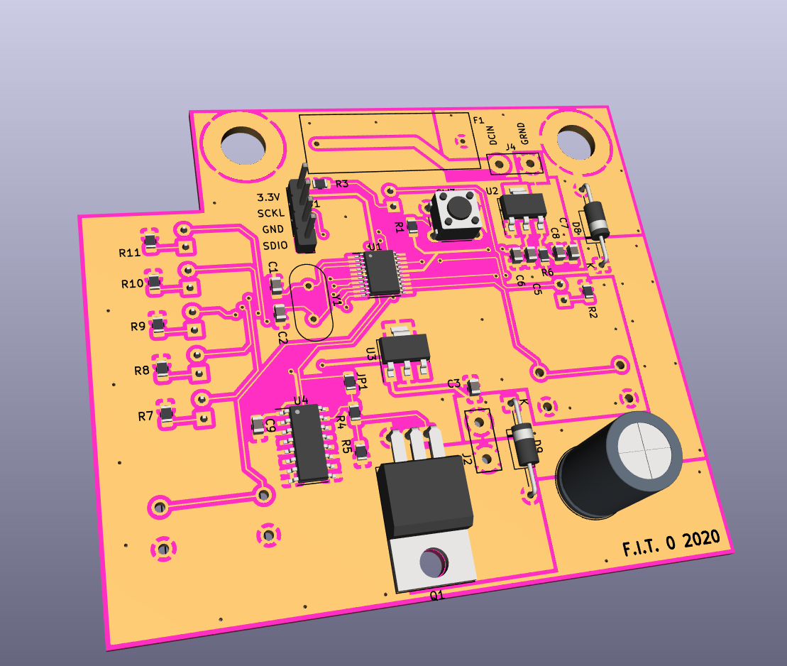
as far as I know the injectors on modern cars are digitally controlled by the on board computer. On my car which is from 2000 it's very rudimentary. The CPU controlled the ON time and the frequency of each injector depending on the various sensor readings (throttle position sensor, crankshaft, air pressure, ...). It's really a digital signal for the command control. However the coil has inertia.
the tester will be useful to determine if the injector channel is clogged or has debris in it. The test pattern could be useful to see if the coil is responding at different speed. On this project there will be a mode were the channel is always on to allow cleaner substance to go through.