 Ken Meyer
I had a great project update ready this weekend, but when I stopped working on it for a while to attend to real life, my computer decided to reboot (even though I have it set to manual update only!). I suppose that's the price for using an alpha service like this that doesn't allow draft updates!
Anyway, I'll give an abbreviated update (and I'll probably add some more minor updates instead of trying to write out complete little articles).
As I mentioned before, the HX711 breakout boards I've found work at 5V. That's fine for many applications, but the Apitronics Bees run at 3.3V, and for the prototype, I don't want to mess with other voltages. This will cut the resolution of the system since the signal from a load cell scales linearly with the excitation voltage whereas the noise floor is likely to stay roughly constant. However, adding a higher voltage (probably 10-12V just to energize the load cell presents another set of complications. The resolution is technically going to be higher, but without really careful engineering, the temperature sensitivity could get out of hand if the 10V regulator drifted relative to the 3.3V regulator in the Apitronics Bee, or worse, the 1.25V voltage reference in the HX711 chip.
I'd rather lose sensitivity in my early prototype than have additional complex temperature coefficients, so I'm going to just drop the HX711 excitation voltage to 3.3V for now.
Another, less temperature-sensitive method would be to run the board at 5V (the HX711 chip can't take more than 5.5V) and simply use a level shifter board to get the signal back to the Apitronics Bee, but again, if I can manage to do this prototype without adding more regulators and breakout boards, I'll keep it simple at the expense of some resolution.
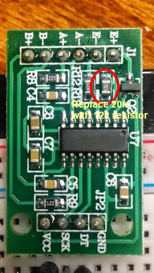
Here's a picture of my breakout board showing the resistor that needs to be swapped out with a 12k resistor to drop the excitation voltage (E+ to E-) from 4.35V down to around 3.1V (at least 0.1V below the input voltage of 3.3V). This is based on the equation in the HX71`1 datasheet that gives voltage as VAVDD=VBG*(R1+R2)/ R1. Note that this equation in the datasheet is wrong and gets the simple voltage divider backwards -- R1 and R2 should be swapped either in the equation or in figure 1 (!) to get near the measured 4.35V rather than well under 2V.
A quick calculation (with the error corrected) shows that swapping the 20k Ohm resistor (R12 on the board and on the schematic here) with a 12k Ohm resistor should drop the voltage to 3.1V. I pulled out my trusty soldering iron and Voila, the voltage dropped to 3.14V, just as expected!
Another quick note: while this breakout board is usually marketed as a 5V board (mainly due to the values of R12 and R13, there's no reason it won't work at 3.3V since the HX711 is well within specification at that voltage. I'll admit, it's possible there's something I haven't thought of that will cause a problem when I hook it up to the lower voltage, but I'll give it a quick test with a protected voltage supply before hooking it up to the Apitronics Bee.
[EDIT 27 Sep 14] I noticed that the input voltage can droop to as low as 3.0V for some reason. It could be an issue with the power regulator, or some excessive resistance in my setup (which includes a cheap breadboard) or maybe my cheap multimeter is off. Still, I wanted to be safe, so I swapped out the 12k Ohm resistor I put in for a lower, 10k Ohm resistor for an excitation of around 2.8V.
Discussions
Become a Hackaday.io Member
Create an account to leave a comment. Already have an account? Log In.
Thank you for the excellent detail. I found it most helpful in debugging why our HX711 modules were giving wildly fluctuating numbers. In then end I took a number of voltage measurements both before and after modifications. This allowed me to make a simple spreadsheet to properly optimize the values of resistor. We found it easier to just piggyback a second resistor in parallel rather than replace the original completely. It turned out that adding a 22K resistor on top gave a 10.48K net. That resulted in 2.9v and gave perfect results.
By the way, we started our project in early 2018 without knowing about yours and only found yours a few months ago. It has been fun for me to see the similarities and difference between the approach to our two projects. I hope your system is still running smoothly. We hope to have about 6 or 8 of ours working before the fall season so we can watch honey production and use over the winter.
Are you sure? yes | no