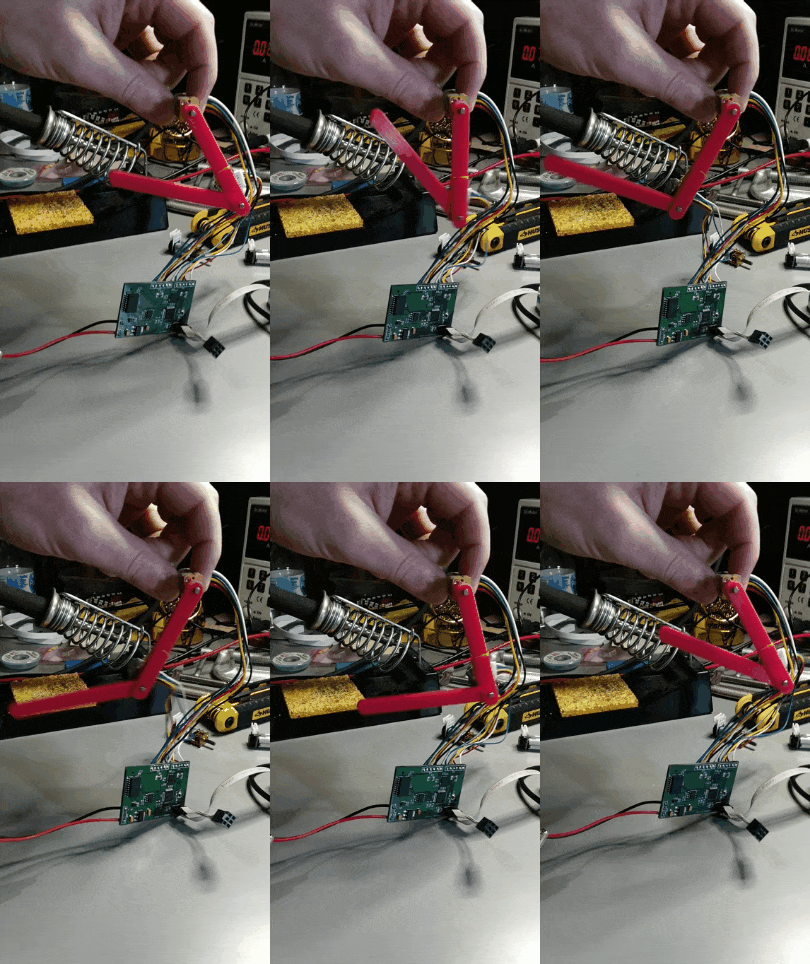
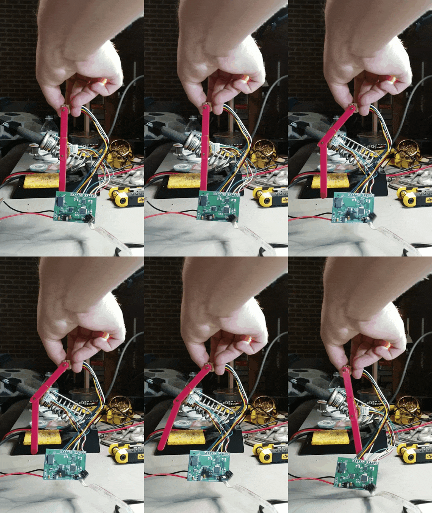
This log is mostly focused on the code needed to achieve this: tracking of a circle with a 2-jointed robotic leg.

The first step to achieving this is setting up the drivers for interacting with the motor. I am using the ATSAMD21 microcontroller and using the Atmel Studio IDE for the firmware development. In order to make multitasking easier, I am running FreeRTOS. If you have never used a real-time operating system (RTOS) on a microcontroller project, I highly recommend you try one out. In exchange for some added complexity on setup, an RTOS makes many common tasks much easier to implement. To speed development, I am also using Microchip's Advanced Software Framework (ASF) driver support.
To interact with the motors, we need to set up the External Interrupt Controller (EIC) module to decode the signals from the quadrature encoders. Sparkfun has a great document laying out the states of a quadrature encoder and what transitions should be considered as moving forward or backward. The following code snippet implements this. This is an ISR triggered at every state transition of the 4 encoder pins. In the future I could speed this up by monitoring which pin triggered the ISR and only responding to that event, but it seems OK for now.
void extint_detection_callback(void)
 {
     bool m1_in1_state = port_pin_get_input_level(MOTOR_1_IN1_GPIO);
     bool m1_in2_state = port_pin_get_input_level(MOTOR_1_IN2_GPIO);
     bool m2_in1_state = port_pin_get_input_level(MOTOR_2_IN1_GPIO);
     bool m2_in2_state = port_pin_get_input_level(MOTOR_2_IN2_GPIO);

     // get state
     encoder_state[0] = ((m1_in1_state & 0x01) << 0x00) | ((m1_in2_state & 0x01) << 0x01);
     encoder_state[1] = ((m2_in1_state & 0x01) << 0x00) | ((m2_in2_state & 0x01) << 0x01);

     // increment if needed
     int32_t i;
     for(i = 0; i < NUMBER_MOTORS; i++)
     {
         switch(encoder_state[i])
         {
             case 0:
                 if(last_encoder_state[i] == 2)
                 {
                     ticks_count[i]--;
                 }
                 else if(last_encoder_state[i] == 1)
                 {
                     ticks_count[i]++;
                 }
                 break;
             case 1:
                 if(last_encoder_state[i] == 0)
                 {
                     ticks_count[i]--;
                 }
                 else if(last_encoder_state[i] == 3)
                 {
                     ticks_count[i]++;
                 }
                 break;
             case 2:
                 if(last_encoder_state[i] == 3)
                 {
                    ticks_count[i]--;
                 }
                 else if(last_encoder_state[i] == 0)
                 {
                    ticks_count[i]++;
                 }
                 break;
             case 3:
                 if(last_encoder_state[i] == 1)
                 {
                     ticks_count[i]--;
                 }
                 else if(last_encoder_state[i] == 2)
                 {
                     ticks_count[i]++;
                 }
                 break;
             default:
                break;
         }
         // Save state
         last_encoder_state[i] = encoder_state[i];
     }
 }
Next, we need a way to control the motor. I have used the A3906 dual motor controller. By applying a PWM signal to the appropriate pins on the motor controller, I can apply various levels of drive effort to the motor. I am using the SAMD21's Timer/Counter for Control Applications (TCC) module for this. With the SAMD21's highly configurable clocks, I can choose a wide variety of PWM frequencies and resolutions. I have set up the system to run at ~4.8kHz with a resolution of 10,000 ticks. This code snippet shows how to set up the module. If you use this as well, be careful of how TCC maps a limited number of channels to a larger amount of pins.
        struct tcc_config config_tcc;
    tcc_get_config_defaults(&config_tcc, TCC0);
    config_tcc.counter.clock_source = GCLK_GENERATOR_0; // 48 MHz
    config_tcc.counter.clock_prescaler = TCC_CLOCK_PRESCALER_DIV1; // PWM freq = clk / (N (TOP + 1)), where N is prescaler
    config_tcc.counter.period = PWM_PERIOD;
    config_tcc.compare.wave_generation = TCC_WAVE_GENERATION_SINGLE_SLOPE_PWM;

    config_tcc.compare.match[1] = 0; // channel 1 mapped to pin 5
    config_tcc.pins.enable_wave_out_pin[5] = true;
    config_tcc.pins.wave_out_pin[5]        = MOTOR_1_CONTROL1_GPIO;
    config_tcc.pins.wave_out_pin_mux[5]    = PINMUX_PA15F_TCC0_WO5;
    config_tcc.wave_ext.invert[5] = true;

    config_tcc.compare.match[0] = 0; // channel 0 mapped to pin 4
    config_tcc.pins.enable_wave_out_pin[4] = true;
    config_tcc.pins.wave_out_pin[4]        = MOTOR_1_CONTROL2_GPIO;
    config_tcc.pins.wave_out_pin_mux[4]    = PINMUX_PA14F_TCC0_WO4;
    config_tcc.wave_ext.invert[4] = true;

    tcc_init(&tcc_instance_0, TCC0, &config_tcc);
    tcc_enable(&tcc_instance_0);
Finally, I have current monitoring on both motors, so I set up the ADC in callback mode. Essentially, the ADC is set up to continuously measure the voltage on current shunt resistors with minimal CPU time needed. The snippet below shows the ADC setup. We scan pins 16 and 17.
 void adc_interface_init(void)
 {
    struct adc_config config;

    adc_get_config_defaults(&config);
    config.positive_input = ADC_POSITIVE_INPUT_PIN16;
    config.negative_input = ADC_NEGATIVE_INPUT_GND;
    config.differential_mode = false;
    config.clock_source = GCLK_GENERATOR_1;
    config.clock_prescaler = ADC_CLOCK_PRESCALER_DIV512;
    config.gain_factor = ADC_GAIN_FACTOR_2X;
    config.resolution = ADC_RESOLUTION_12BIT;
    config.reference = ADC_REFERENCE_INT1V; // 3.3V

    // Scan from 16-17
    config.pin_scan.offset_start_scan = 0;
    config.pin_scan.inputs_to_scan = 2;

    adc_init(&adc_module_instance, ADC, &config);
    adc_enable(&adc_module_instance);

    // Handle all conversions in callbacks
    adc_register_callback(&adc_module_instance, adc_cb, ADC_CALLBACK_READ_BUFFER);
    adc_enable_callback(&adc_module_instance, ADC_CALLBACK_READ_BUFFER);

    adc_read_buffer_job(&adc_module_instance, adc_buffer, ADC_BUFFER_SIZE);
 }
Once the hardware is set up, we need to set up a basic motor controller. PID control is one of the simplest yet most effective control methods, and one of the best theoretically understood. However, some care must be taken with implementation. A textbook PID controller looks like this:
The control effort u (here the PWM duty cycle sent to the motor) is equal to some constant k_p multiplied by the error (proportional to the error, P in PID) plus some constant k_d multiplied by the rate of change of the error (the derivative of the error, D in PID) plus a third constant k_i multiplied by the integral of the error (I in PID). However, that textbook implementation implies continuous time but in code we need a discrete time implementation. We do not have derivatives, we have differences. Instead of integrals, we have sums. In addition, we can't provide more than 100% power to the motor. This saturation event is not considered in most textbook implementations or analysis of PID control. For a realistic discrete time PID controller, a few things should be added: derivative filtering and integral anti-windup. Other additions like integral operation zones and effort limiting are also good ideas. My implemented PID controller looks like this:
float calculate_pid(pid_control_t * pid, int32_t setpoint, int32_t current_position)
 {
    float error = setpoint - current_position;

    pid->speed = (pid->speed_alpha)*pid->speed + (1.0-pid->speed_alpha)*(error - pid->last_error);

    pid->integral += error;

    if(pid->integral > pid->integral_max)
    {
        pid->integral = pid->integral_max;
    }
    else if(pid->integral < pid->integral_min)
    {
        pid->integral = pid->integral_min;
    }

    float cmd = pid->kp * error + pid->kd * pid->speed + pid->ki * pid->integral;

    if(cmd > pid->cmd_max)
    {
        cmd    = pid->cmd_max;
    }
    else if(cmd < pid->cmd_min)
    {
        cmd = pid->cmd_min;
    }

    pid->last_error = error;
    return cmd;
 }
For now as a demo, I am only using the controller as a pure proportional controller. With that, I can control to various positions, as shown next. At this point, I have effectively built a dual servo motor controller.

The final step to achieve more complex positional tracking is to implement inverse kinematics. To understand why this is important, consider how we typically think of a "position." We may think of driving 2 miles south, and half a mile east and intuitively understand that. Disregarding the complexities on a larger scale of not having a flat Earth, we can think of that as moving along a flat surface with north-south and east-west as the two directions. We can describe any position on that surface by this Cartesian reference frame. We can think of a similar reference frame attached to the thigh joint on this robotic leg. Positive X direction is forward and positive Y direction is down. The first gif here shows the foot tracking a circle in that frame. However, this is not how the motors think. They control to an angle. But a position in the Cartesian Frame (x,y) and the position in the Joint Frame are obviously related. They are related by kinematics. Kinematics are geometric relations describing the mapping between these two reference frames. Kinematics maps from the Joint Frame to the Cartesian Frame while inverse kinematics does the reverse.
Unfortunately, it is not that easy. Our two-joint leg is simple, but with more joints this mapping can get very complicated. There can be multiple solutions, no solutions, and other issues, but we won't get into that. For this leg, it is a common two-link arm, and the solution is shown here:
Again, this does not guarantee all solutions exist, but for reasonable inputs it is OK.
Using these inverse kinematic equations, we can now map a circle from the Cartesian Frame to Joint Space. This section is quite simple:
leg_ik_t leg;
leg.thigh_length_m = 0.060;
leg.calf_length_m = 0.075;
init_leg_precalcs(&leg);

float x_off = 0.045;
float y_off = 0.080;
float omega = 2.0;

 vTaskDelay(pdMS_TO_TICKS(2000));

 for (;;)
 {

     // Inverse kinematics track circle
      vTaskDelay(20);
     float t = xTaskGetTickCount() * 0.001; // In seconds
     float xd = x_off + 0.04 * sin( omega * t );
     float yd = y_off + 0.04 * cos( omega * t );

     pos_cartesian_t cart_pos;
     cart_pos.x = xd;
     cart_pos.y = yd;

     pos_joint_space_t js_pos;
     calculate_ik(&leg, &js_pos, cart_pos);

     set_motor_position(RAD_TO_DEG * js_pos.thigh_angle_rad, 0);
     set_motor_position(RAD_TO_DEG * js_pos.knee_angle_rad, 1);

}
Every 20 ms a new point is picked to track to, and the PID controllers drive both motors to the desired position.
That's it! We now have the dual motor controller tracking Cartesian inputs using inverse kinematics. There are a few key future efforts:
- Design revision to fix CAN to allow main controller to control more than 2 motors at a time
- Adding a impedance/virtual model controller, like those used on many ambulatory robots like the MIT Cheetah
Discussions
Become a Hackaday.io Member
Create an account to leave a comment. Already have an account? Log In.