The last log covered the implementation of position PID control, then inverse kinematics which allow the system to track a motion in the Cartesian space. As another demo, I tried increasing the frequency of actuation. This leg is hauling. This is really where this project is much better than hobby servos: it can go faster and all parameters can be tuned. Note I also bought some steel hubs which greatly reduce the backlash in the leg.
Just as position control is a prerequisite for a tracking controller with inverse kinematics, those same inverse kinematics and current control are prerequisites for a Virtual Model/Impedance Controller.
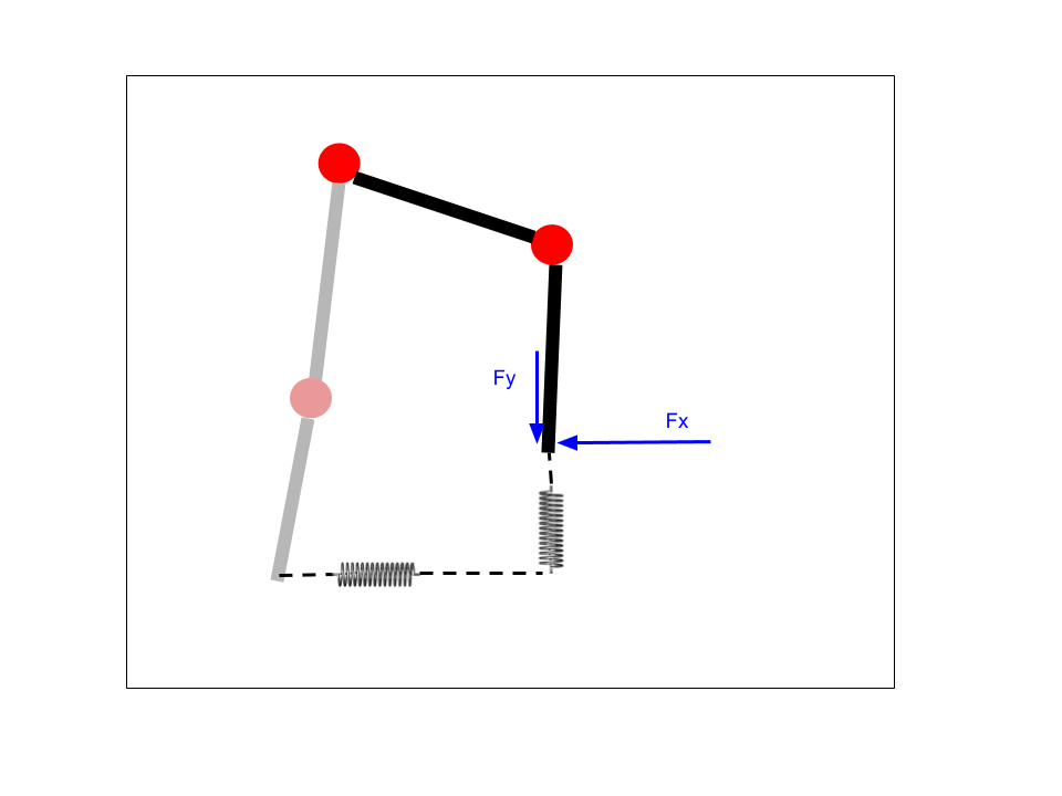
The Virtual Model Controller implemented here is a simple Cartesian spring setup. The idea is that there are virtual springs attached between the real "foot" of the leg and some desired position for the leg to be. Based on the Hooke's Law for linear springs, we then calculate a desired force to apply to the foot. We then calculate the appropriate torque needed at each joint to apply that force. Depending on the environment, there may be nothing to push against to achieve that force, but this setup nonetheless allows for a pseudo-position control as well, as the foot will be "pulled" towards the desired position by the virtual springs. For ambulatory robots, this sort of controller is common, as it adds virtual elasticity which can help stabilize the walking controller.
In the simplest motor models, motor current is proportional to motor torque. In ambulatory robots, this is often used to achieve torque control via motor current control. This works well with high-quality motors, low friction, and minimal gearing. The cheap, highly geared motors I am using are not ideal, to say the least. Furthermore, I do not have directional current sensing, which during transitions between direction can cause issues. Nonetheless, we will look at how the implementation would be achieved.
Current Control
The current control is implemented using the previously shown PID control library, but instead of providing encoder ticks inputs I use current in mA. Since I do not have directional current measurement, I don't want to allow the controller to command an opposite direction command, which could destabilize the controller. Instead, it clamps the command to zero. In reality, this should be OK, as the current will drop rapidly if command is set to zero. As a demo, I set a motor to drive +100mA and then -200mA periodically. The gifs below show the current being limited appropriately. It is not perfectly tuned, but is certainly working.
Note that unless the motor pushes against something, it likely will not reach the desired current, and will simply spin in the correct direction indefinitely. This can be a challenge with the virtual model controller. If the controller is not fast enough, the leg will move so much that instabilities in the controller can be reached.
Virtual Model Controller
Assuming that current control is linearly equivalent to torque control (again, not very true for these motors, but they are related) the next step is to be able to transform desired force in the Cartesian frame to desired torque in joint space. This is directly related to the inverse kinematics discussed previously. Ignoring friction, gravity, and other forces, the transformation uses the Jacobian, which here is the partial derivatives of the positions with respect to the motor orientations. The values of this matrix change as the leg moves, so it must be recalculated online. Then, the torque can be calculated from the forces with the transpose of the Jacobian.
The code for this looks like the following:
 void calculate_impedance_control(const impedance_control_params_t params, const leg_ik_t leg, const pos_joint_space_t current_pos, const pos_cartesian_t desired_pos, impedance_control_cmds_t * cmds)
 {
	pos_cartesian_t current_pos_cart;
	calculate_fk(&leg, ¤t_pos_cart, current_pos);

	// Calculate desired force from springs
	// TODO add damper
	float fx = params.k_eff * (desired_pos.x - current_pos_cart.x); // In N
	float fy = params.k_eff * (desired_pos.y - current_pos_cart.y);

	// Calculate jacobian
	float j_01 = -leg.calf_length_m * sin(current_pos.thigh_angle_rad + current_pos.knee_angle_rad);
	float j_00 = -leg.thigh_length_m * sin(current_pos.thigh_angle_rad) + j_01;
	float j_11 = leg.calf_length_m * cos(current_pos.thigh_angle_rad + current_pos.knee_angle_rad);
	float j_10 = leg.thigh_length_m * cos(current_pos.thigh_angle_rad) + j_11;

	// Calculate desired torque, tau_d = J^T * f_d
	float tau_hip = fx*j_00 + fy*j_10; // In N * m
	float tau_knee = fx*j_01 + fy*j_11;

	// Account for gear ratio
	tau_hip = tau_hip / params.gear_ratio;
	tau_knee = tau_knee / params.gear_ratio;

	// Calculate desired current to meet torque
	float current_hip = params.gain_current_per_torque * tau_hip;
	float current_knee = params.gain_current_per_torque * tau_knee;

	// Current controller outside of here
	cmds->hip_cmd_ma = current_hip * 1000.0;
	cmds->knee_cmd_ma = current_knee * 1000.0;
 }
The desired force is calculated, then the corresponding torque is calculated, then the appropriate motor current is determined. Not shown here is the current control that is finally applied.
Overall, this approach *sort of* works. As a test, I used the same desired circular motion as the desired position of the foot, then this impedance controller to pull the foot in that motion. It is not well tuned, and with these cheap motors with large gear ratios I don't expect good results but the leg does move approximately correctly. When I push and pull against the foot, it is more obvious how the controller wants the foot to move.
Next I will be working on the CAN bus network layer. On this version of the PCB, I forgot the crystal oscillator for the CAN controller, but I think I may be able to bodge wire a clock from the SAMD21 to the controller and get it to work.
Discussions
Become a Hackaday.io Member
Create an account to leave a comment. Already have an account? Log In.