With the project now able to control two motors well, and much of the supporting code for more complicated use cases written, the next step is to set up the communication between devices. For this, the Controller Area Network (CAN) bus is used. Originally developed for automotive use, CAN allows for relatively high-speed, robust, and long-range multi-master communication. It uses two wires which are differentially driven by a dedicated transceiver. I used the TCAN334 here. While some microcontrollers have a CAN controller built in, the ATSAMD21 does not, so I used the ubiquitous MCP2515. The MCP2515 is commonly used in all sorts of low-cost hobbyist (and serious commercial) CAN applications. It has an SPI interface to the ATSAMD21. The two steps here are writing the code to support commands over CAN, and wiring up the physical interface.
CAN Network Software Implementation
The Wikipedia page for CAN bus is very enlightening if you are not familiar with how CAN works. CAN is a multi-master protocol, so any device on the bus can send a frame at any time. Each frame has many parts, but the most important are the Identifier (ID) and data sections. The ID is either a 11 or 29 bit value that indicates what is in the message. The data section then holds 0-8 bytes of message data. At the lowest level, the IDs don't mean anything, it is up to the developer to determine how they should be set up. To de-conflict messages, lower ID values are sent first and are thus higher priority messages. When determining how to lay out the IDs, this should be accounted for and lower IDs used for higher priority messages. Finally, different nodes on the bus should never try to send frames with the same ID.
Therefore, we take some inspiration from the way that the FIRST Robotics Competition lays out IDs using sections of the ID bitfield. Unlike FRC, we will use standard (11 bit) identifiers and communicate at 500kbps (may increase speed in the future). We use the most significant bit as a message type identifier: either a command or info frame. Therefore, all commands are higher priority than all info messages. The next most significant 3 bits are a message class identifier. The next 3 most significant bits are message indices. Finally, the last 4 bits are device indices. For commands, the device index indicates the receiver. For info messages, the device index indicates the sender.
I then started to think about what messages I would want to send. These can and will be changed in the future but I started with the following:
#define CAN_MSG_TYPE_SHIFT				(10ul)
#define CAN_MSG_TYPE_MASK				(1ul << CAN_MSG_TYPE_SHIFT)

#define CAN_MSG_CLASS_SHIFT				(7ul)
#define CAN_MSG_CLASS_MASK				(7ul << CAN_MSG_CLASS_SHIFT)

#define CAN_MSG_INDEX_SHIFT				(4ul)
#define CAN_MSG_INDEX_MASK				(7ul << CAN_MSG_INDEX_SHIFT)

#define CAN_MSG_DEVICE_SHIFT			(0ul)
#define CAN_MSG_DEVICE_MASK				(15ul << CAN_MSG_DEVICE_SHIFT)

#define CAN_MSG_TYPE_CMD					(0)
#define CAN_MSG_TYPE_INFO					(1)

#define CAN_MSG_CLASS_CMD_CONTROL			(0)
#define CAN_MSG_CLASS_CMD_TIME				(1)
#define CAN_MSG_CLASS_CMD_SET_PARAM			(2)

#define CAN_MSG_INDEX_CMD_POSITION			(0)
#define CAN_MSG_INDEX_CMD_SPEED				(1)
#define CAN_MSG_INDEX_CMD_CURRENT			(2)
#define CAN_MSG_INDEX_CMD_PRIMITIVE			(3)

#define CAN_MSG_CLASS_INFO_TELEMETRY		(0)

#define CAN_MSG_INDEX_INFO_POSITION			(0)
#define CAN_MSG_INDEX_INFO_CURRENT			(1)
#define CAN_MSG_INDEX_INFO_SPEED			(2)
There are three obvious command classes I might want: control commands, time (for synchronization), and setting parameters. Then, within control I might want position, speed, current, or motion primitive commands.
Within info, there are numerous telemetry messages we could send. To start, I listed motor position, current, and speed.
This does not currently show how the data in these messages are packed, I will need to create an ICD for that.
The first one to implement support for is a position command. I will set up an Arduino Uno + CAN bus shield to generate and send position commands, and my controller board will act upon those commands. This message will be packed such that the first byte is the motor index (0 or 1), and the next 4 bytes are a float packed as little-endian. This frame is only 5 bytes long.
CAN Network Wiring
The main reason I had held off on this step for so long was a design mistake I had made. I had forgotten to add the oscillator required by the MCP2515, which would surely cause it to not function correctly. To solve this on my current board, I realized one of the motor controller flag pins was mapped to the ATSAMD21 general clock #6. The MCP2515 can operate with either an oscillator or an external clock. I therefore could cut the trace to the motor controller and bodge wire the pin to the MCP2515 clock-in pin. The yellow wire on the PCB is doing this.
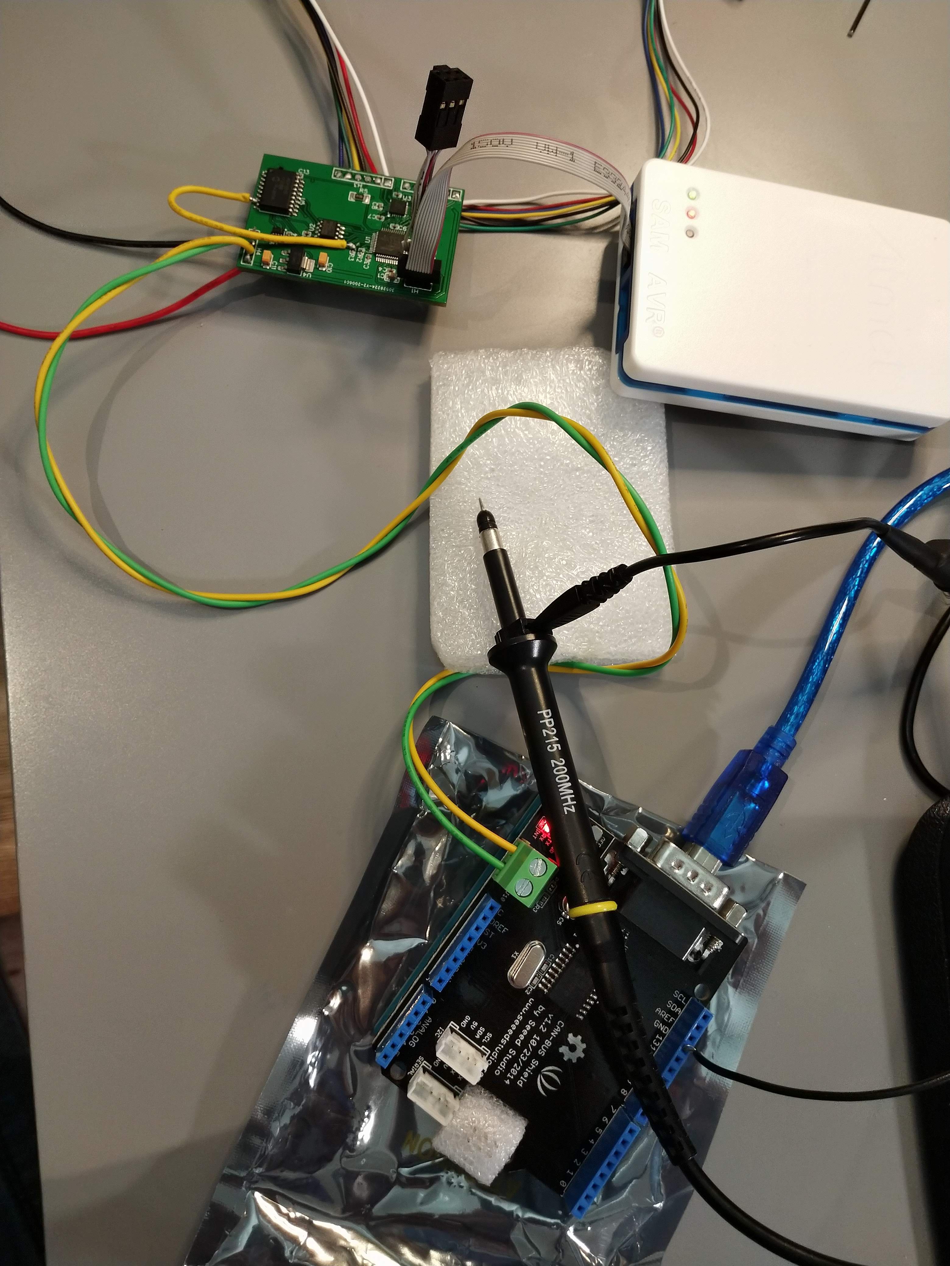
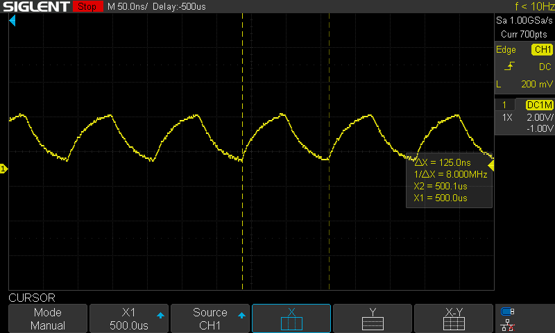
Unfortunately, when I probed the signal with my oscilloscope, the clock is a sawtooth, very not square. It is at the correct, desired 8Mhz. I suspected the controller may not be able to function properly because of this poor signal integrity. Note that the signal is poor with and without the bodge wire attached.
When I wired everything up, I set up an Arduino Uno with CAN bus shield to send motor 0 position commands every 2 seconds. However, when I probe the CANH line, it is clear that a message is being repeatedly sent at ~4kHz.
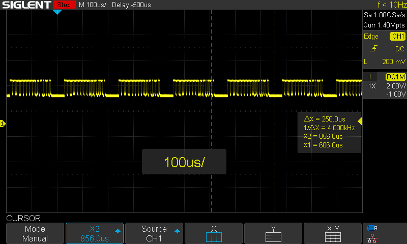
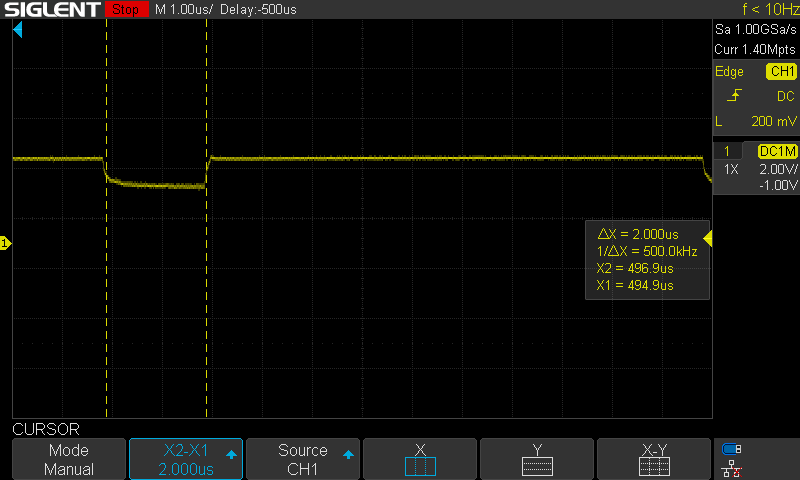
The network is not correctly terminated, with a 100 Ohm resistor on only one side (should be 120 Ohm on both sides), but in my experience such a short run should work regardless. This "spamming" of the network is a common error condition in CAN (depending on the settings of the CAN controller). There is no other device to acknowledge the frame, so it repeatedly sends the frame. This implies that the CAN controller or CAN transceiver on my PCB are not functioning properly. I double checked the polarity of the reset and standby pins for those, and they are correct. This error is likely due to the poor clock signal. I have some other ideas I can try, but I probably will have to do the redesign before I can move forward with the CAN setup.
Discussions
Become a Hackaday.io Member
Create an account to leave a comment. Already have an account? Log In.