Overview
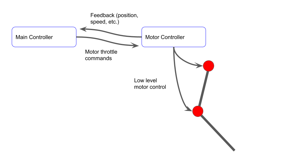
In robotics, online motion planning can be computationally intensive and/or add significant network load. To avoid this, motion primitives are sometimes used. The concept is that the higher level controller can command pre-determined trajectories that the lower level "local" controller can implement. To understand this better, first consider the following picture. Here, the main controller is doing the lower level control of the motors. It receives information about the motor (position, speed, etc.) and calculates motor throttle commands to the motor controller. The motor controller then does the low level control (e.g. PWM control). The communication between the main controller and motor controller must be fast for this to work. In addition, it requires significant computation on the main controller.
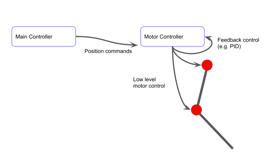
The next option is to offload the lower-level position control to the local controller, but still perform the motion planning on the main controller. This is what I've previously shown, where the ESP32 commands positions over the CAN bus to the dual motor controller. This works, but as the system has more and more motors (currently, we can address 16 motors), the main controller has to work harder to provide near real-time position commands to track trajectories. It could also potentially overload the CAN bus.
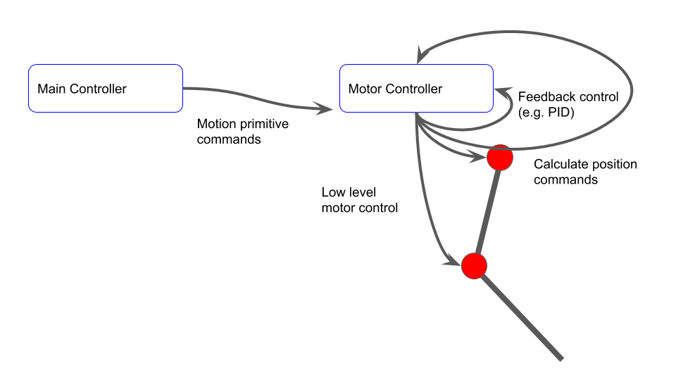
Finally, consider a motion primitive approach. Here, the motion controller simply tells the local controller to follow a pre-determined profile. The local controller then calculates its own position commands online, and controls the motor to follow the trajectory. This can potentially fully offload the main controller and the CAN bus.
While the concept is simple, implementation is more difficult. We will dig into the implementation next.
Implementation
Thankfully, we already have much of the supporting structure needed to implement simple motion primitives. Namely, we have the structure to unpack CAN messages, change control modes, and calculate inverse kinematics of a two-joint leg.
In general, we will need a set of keypoints (provided in cartesian space for ease of understanding), and timing information of each of the keypoints. The primitives will be assumed to be periodic. We want the main controller to be able to slightly modify the primitive if needed. For example, we may want to stretch out a motion in one direction, change the period, or change the phase of the motion (time offset). We also may want to invert the motion to support left vs. right legs. I therefore created a few structures that help define the motion.
typedef struct
{
	float x;
	float y;
	float t_part;
} keyframe_t;

typedef struct
{
	uint8_t num_keyframes;
	uint8_t invert;
	float tau; // period
	float t_offset;
	keyframe_t frames[MAX_NUMBER_KEYFRAMES];
} primitive_t;
I started with a single example primitive, although it should be clear that adding further primitives is straightforward. We have 8 keyframes here. The motion is sort of a pointy, stretched rectangle, with positions in mm. Note that based on the t_part of each keyframe, the section from frame 4 to 5 is the slowest. The thought is that this could be a walking/crawling motion where the leg moves slower while pushing against the ground and faster in mid-air.
void motion_primitive_init(void)
 {
	// Leg straight, motors at zero is leg straight down +x. Forward is +y

	// t_part must be always increasing, never > 1.0. Must be a cyclical motion primitive

	// Curved rectangle primitive
	primitives[0].num_keyframes = 8;
	primitives[0].tau = 2.0;
	primitives[0].t_offset = 0.0;
	primitives[0].invert = 0;
	primitives[0].frames[0].t_part = 0.0 / primitives[0].tau;
	primitives[0].frames[0].x = 0.07;
	primitives[0].frames[0].y = 0.00;

	primitives[0].frames[1].t_part = 0.2 / primitives[0].tau;
	primitives[0].frames[1].x = 0.07;
	primitives[0].frames[1].y = 0.06;

	primitives[0].frames[2].t_part = 0.3 / primitives[0].tau;
	primitives[0].frames[2].x = 0.083;
	primitives[0].frames[2].y = 0.065;

	primitives[0].frames[3].t_part = 0.4 / primitives[0].tau;
	primitives[0].frames[3].x = 0.086;
	primitives[0].frames[3].y = 0.065;

	primitives[0].frames[4].t_part = 0.5 / primitives[0].tau;
	primitives[0].frames[4].x = 0.09;
	primitives[0].frames[4].y = 0.06;

	primitives[0].frames[5].t_part = 1.6 / primitives[0].tau; // Slower on back stroke
	primitives[0].frames[5].x = 0.09;
	primitives[0].frames[5].y = 0.0;

	primitives[0].frames[6].t_part = 1.8 / primitives[0].tau;
	primitives[0].frames[6].x = 0.086;
	primitives[0].frames[6].y = -0.05;

	primitives[0].frames[7].t_part = 1.9 / primitives[0].tau;
	primitives[0].frames[7].x = 0.083;
	primitives[0].frames[7].y = -0.05;
 }
We handle CAN commands for this as shown below. Primitives require both motors. We have the normal control loop in position control mode, and a separate loop periodically updates the desired position according to the primitive profile. From the CAN frame, we determine which primitive to use, the period "Tau" in ms, a time offset in ms, and an indication if the profile should be run inverted (not backwards in time, reversed in joint space.)
else if(msg.can_index == CAN_MSG_INDEX_CMD_PRIMITIVE)
{
	 // Primitives affect both motors
	int16_t tau_ms = 0;
	int16_t t_offset_ms = 0;
	uint8_t primitive_index = can_frame.data[0];
	memcpy(&tau_ms, &can_frame.data[1], 2);
	memcpy(&t_offset_ms, &can_frame.data[3], 2);
	uint8_t invert = can_frame.data[5];
	motion_primitive_set_index(primitive_index);
	motion_primitive_set_timing(primitive_index, (float) tau_ms * 0.001, (float) t_offset_ms * 0.001, invert);
	set_control_mode(PRIMITIVE, 0);
	set_control_mode(PRIMITIVE, 1);
}
Within a software timer, we periodically calculate the joint space positions and command the motors.
static void vPrimitivesTimerCallback( TimerHandle_t xTimer )
  {
	int32_t i;
	// Only calculate if all primitive
	for(i=0; i < NUMBER_MOTORS; i++)
	{
		if(control_type[i] != PRIMITIVE)
		{
			return;
		}
	}

	pos_cartesian_t cart_pos;
	pos_joint_space_t js_pos;

	motion_primitive_get_position(&cart_pos.x, &cart_pos.y);

	calculate_ik(&leg, &js_pos, cart_pos);

	if(motion_primitive_is_inverted())
	{
		 js_pos.thigh_angle_rad = -js_pos.thigh_angle_rad;
		 js_pos.knee_angle_rad = -js_pos.knee_angle_rad;
	}

	set_motor_position(RAD_TO_DEG * js_pos.thigh_angle_rad, 0);
	set_motor_position(RAD_TO_DEG * js_pos.knee_angle_rad, 1);
  }
Within the motion primitives library, we generate these positions by linearly interpolating between keypoints, while accounting for global time offsets (used to sync all controllers), and local primitive time offsets.
 void motion_primitive_get_position(float * x, float * y)
 {
	// First find global time,taking into account time syncs and primitive local offsets
	float current_t = 0.001 * (xTaskGetTickCount() - time_offset) - primitives[primitive_index].t_offset;

	float time_in_cycle = fmod(current_t, primitives[primitive_index].tau);
	float time_in_cycle_part = time_in_cycle / primitives[primitive_index].tau; // Prevent further mults

	// Now find where we are in the cycle and linearly interpolate
	int i;
	for(i = 1; i < primitives[primitive_index].num_keyframes; i++)
	{
		// Are we between keyframes?
		if(time_in_cycle_part >= primitives[primitive_index].frames[i-1].t_part && time_in_cycle_part < primitives[primitive_index].frames[i].t_part)
		{
			// Last value plus section of new value
			float dt = (time_in_cycle_part - primitives[primitive_index].frames[i-1].t_part);
			float d_section_dt = 1.0 / (primitives[primitive_index].frames[i].t_part - primitives[primitive_index].frames[i-1].t_part);
			*x = primitives[primitive_index].frames[i-1].x + (dt * (primitives[primitive_index].frames[i].x - primitives[primitive_index].frames[i-1].x) * d_section_dt);
			*y = primitives[primitive_index].frames[i-1].y + (dt * (primitives[primitive_index].frames[i].y - primitives[primitive_index].frames[i-1].y) * d_section_dt);
			return;
		}
		// Are we at the end, and after last keyframe
		if(i == (primitives[primitive_index].num_keyframes-1) && time_in_cycle_part >= primitives[primitive_index].frames[i].t_part)
		{
			// Last value plus section of new value
			float dt = (time_in_cycle_part - primitives[primitive_index].frames[i].t_part);
			float d_section_dt = 1.0 / (1.0 - primitives[primitive_index].frames[i].t_part);
			*x = primitives[primitive_index].frames[i].x + (dt * (primitives[primitive_index].frames[0].x - primitives[primitive_index].frames[i].x) * d_section_dt); // Cyclical, so zero index is next frame at end
			*y = primitives[primitive_index].frames[i].y + (dt * (primitives[primitive_index].frames[0].y - primitives[primitive_index].frames[i].y) * d_section_dt);
			return;
		}
	}
 }
That is all there is to it!
Demo
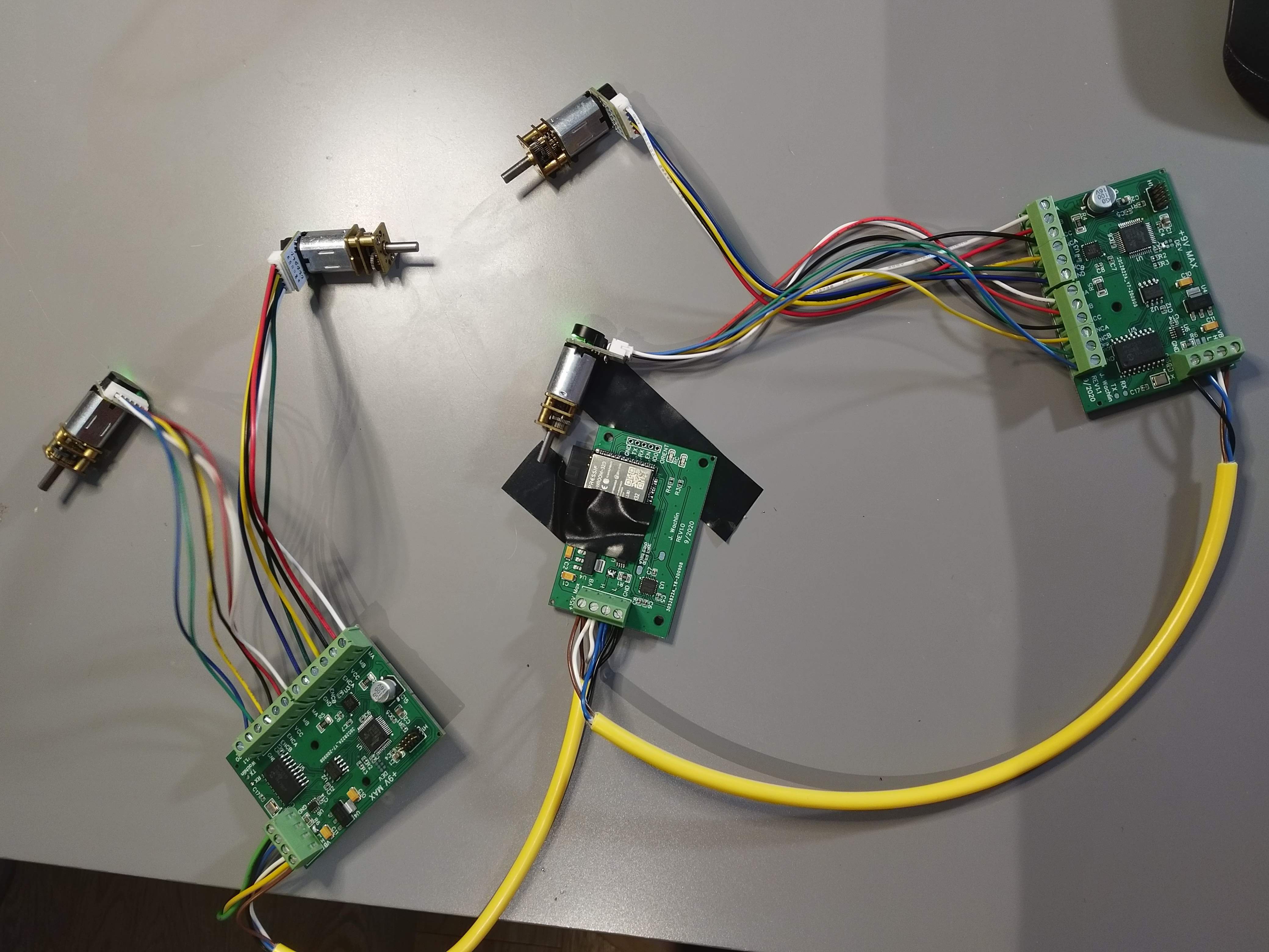
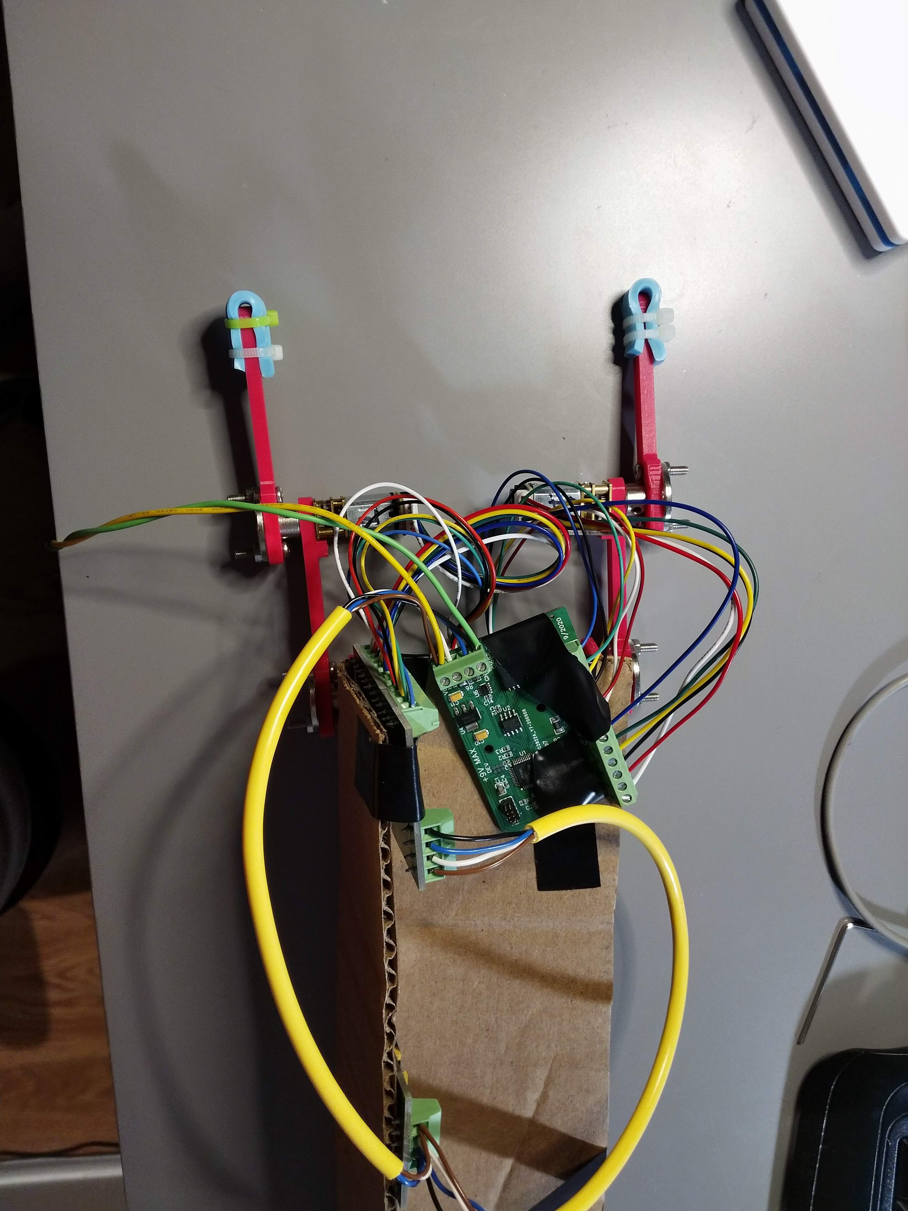
To prepare to test this, I also made some updates to support multiple dual motor controllers on the same network. I provided 3 solder jumpers on the PCB that are used to set the device index in a binary representation. The main controller is index 0, and the first dual motor controller is index 1 if all solder jumpers are open. I soldered one on one controller to set it to index 2. I can then string together many dual motor controllers on the same bus.
The main controller has a very simple job. It simply sends a single command to each controller to begin motion primitive 0. This is done as follows. Devices 1 and 2 are commanded to run primitive #0, with a period of 2s. Device 2 has a time offset of 0.3s. Device 1 is inverted.
#include <CAN.h>
#include "dual_motor_can.h"

#define CAN_RX_PIN      4
#define CAN_TX_PIN      5
#define LED2_PIN              16

void send_primitive_command(uint8_t device, uint8_t primitive, uint8_t invert, int16_t tau_ms, int16_t t_offset_ms)
{
  if(device > 7)
  {
    return;
  }


  uint32_t id = (CAN_MSG_TYPE_CMD << CAN_MSG_TYPE_SHIFT);
  id |= (CAN_MSG_CLASS_CMD_CONTROL << CAN_MSG_CLASS_SHIFT);
  id |= (CAN_MSG_INDEX_CMD_PRIMITIVE << CAN_MSG_INDEX_SHIFT);
  id |= (device << CAN_MSG_DEVICE_SHIFT);

  uint8_t buffer[6];
  buffer[0] = primitive;
  memcpy(&buffer[1], &tau_ms, 2);
  memcpy(&buffer[3], &t_offset_ms, 2);
  buffer[5] = invert;

  CAN.beginPacket(id);
  CAN.write(buffer, 6);
  CAN.endPacket();
}

void setup() {
  Serial.begin(115200);

  Serial.println("CAN position control demo");

  CAN.setPins(CAN_RX_PIN, CAN_TX_PIN);

  // start the CAN bus at 1000 kbps
  if (!CAN.begin(1000E3)) {
    Serial.println("Starting CAN failed!");
    while (1);
  }

  delay(2000);
  send_primitive_command(1, 0, 1, 2000, 0); // Inverted
  delay(20);
  send_primitive_command(2, 0, 0, 2000, 300);
}

void loop() {
  // Do nothing
  delay(1000);
}
After testing that this system works as expected, I attached the 3D printed frame and legs I had previously made. Using tape, zipties, and cardboard, I also hacked together a janky "tail dragger" frame to stabilize the system.
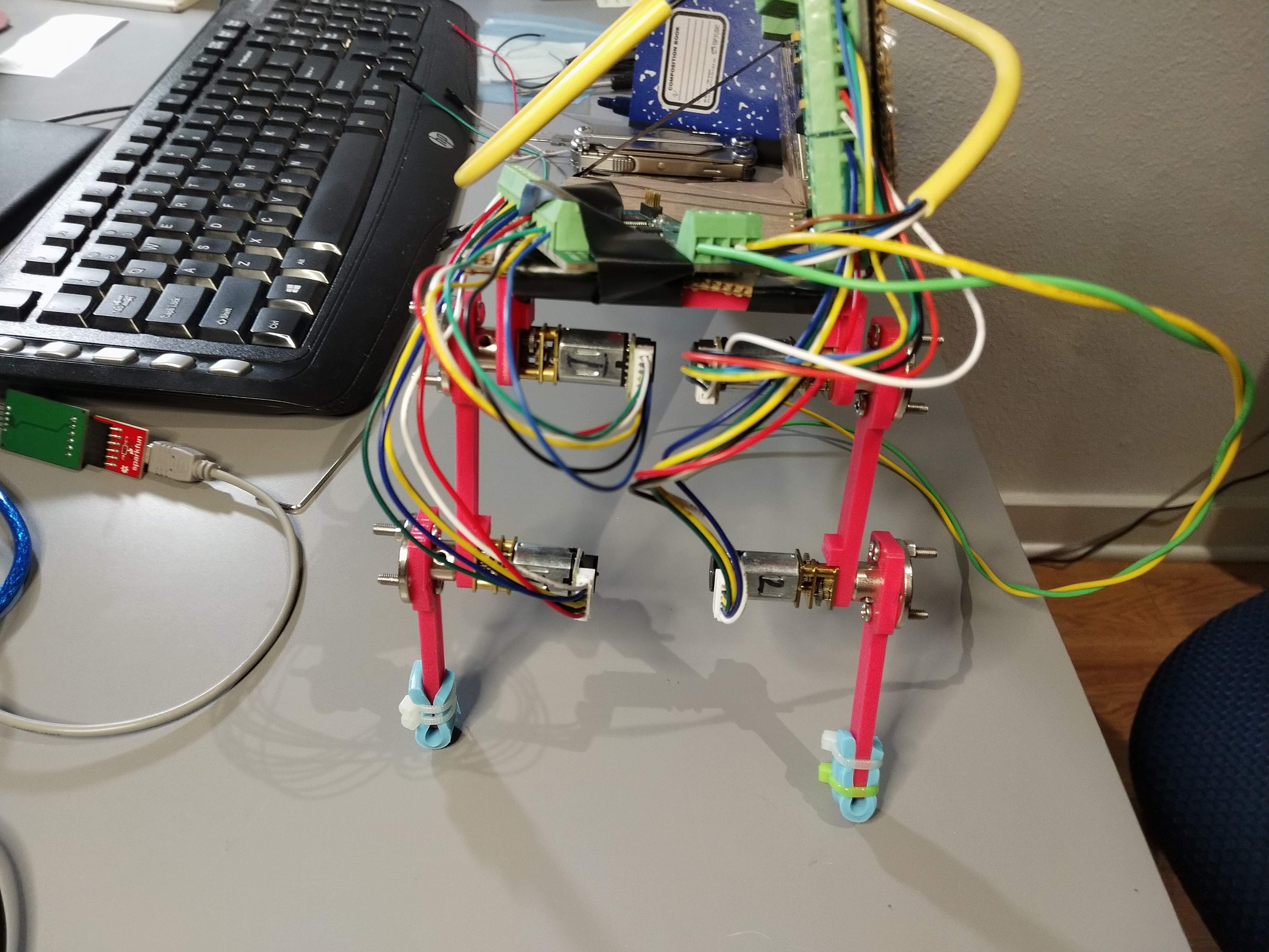
The video below shows the motion in the air. It is clear that the motion is slower pulling back, and that the two legs run at a time offset. Again, since we are using a motion primitive, this motion is occurring with no load on the main controller or CAN bus.
The next video shows the system on the ground. Clearly it is failing to move properly, but not bad for the first attempt.
Future Upgrades
- Precompute motion in joint space to reduce online inverse kinematics computation
- Different interpolation? Interpolate in joint space?
- Additional motion primitives
- Modify motion primitive to achieve crawling
- Support further primitive parameterization
- Support running primitives backwards in time
Discussions
Become a Hackaday.io Member
Create an account to leave a comment. Already have an account? Log In.