 JTKLENKE
The scimitar seemed unlikely to work well enough to meet the requirements for a few reasons. First, the antenna were larger than would fit in the space and still weren't even close to the goal. Also, scimitars are usually used for narrow high frequency ranges and are seemingly cant work well in lower ranges as I'd hoped. While there are a few options for existing designs to optimize (a U like design, multiple vertical wires, scimitar variants and trapezoidal shapes) I really wanted to see if a generalized antenna evolver would work.
I started by defining a rectangle that bounded where points could be, about 25cm tall and 60cm wide and defined a shape that would be on every antenna a 2cm by 1cm triangle where the antenna would be attached (with an alligator clip for testing but eventually soldered). Then, I defined an individual as a collection of points (a 2 by N matrix to represent the x and y position of N points) in the order that they would be connected by wires which would outline a shape. For example, an individual with a matrix of points like this:
[[ 0.          0.        ]
 [ 0.01        0.01      ]
 [ 0.1056655   0.2056655 ]
 [ 0.262       0.32031084]
 [ 0.262       0.4673137 ]
 [ 0.262       0.60390589]
 [ -.1347361   0.70804492]
 [-0.01        0.01      ]
 [ 0.          0.        ]]
would have an outline of:
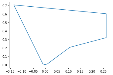
Notice the small triangle at the bottom of the antenna, that's the preset shape that allows the antenna to be attached, every matrix has the points (0,0) and (0.01 , 0.01) at the beginning and a similar set of points at the end to define that shape. Then I just have to modify the testing code a bit to make it take in the new kind of individual and I can run the code as is. Just kidding. There's one big problem, my code cant really handle geometry errors. If two wires cross it breaks, if two wires are too close together it breaks, if the wires are in certain configurations it returns negative VSWRs (it breaks). Luckily, all the necpp functions return an int, 0 if it ran without errors, and some other number if there was an error (different numbers for different errors). I can find negative VSWRs because the real component of the impedance is negative. I use that result to check if there are any errors when calling a function and if there are, I give the broken antenna a high VSWR which should make it worse than any working antenna. I didn't have to do this for the scimitars because I set the limits on the individuals such that they would all give working shapes.
Discussions
Become a Hackaday.io Member
Create an account to leave a comment. Already have an account? Log In.