 Bharbour
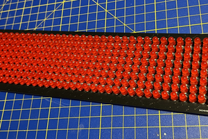
These LiteOn LTP2558AA LED modules came from the local surplus shop (www.elliottelectronicsupply.com/featured/liteon-ltp2558aa-ra-large-2-4x1-5inch-dot-matrix-red-orange-and-green-leds-gray-face-with-white-dots-in-off-state.html). They have a LOT of these beasts in stock. Usable data sheets were found on the LiteOn web site.

This is my first dive into matrix LED stuff. Driving them seems a little bit like driving a video display, but only sort of. I looked at options for driving them from raw drivers and a SPI interface to fully integrated controller/driver chips. In order to support the red and green LEDs, there are two separate sets of row and column pins on each module. Each of the matrices has its own driver chip. The ISSI IS32FL3738 chips support up to a 6x8 matrix, provide current control and dimming options and two of them will fit on a PCB that sits under each module. They are also readily available and fairly inexpensive. I roughed out an electronic design and laid out a 4 layer PCB to mess with.

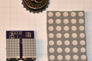
The boards came back from OSH Park and I built up the first one. The two LED controller chips are visible in the center of the board and the I2C address translator (LTC4316) at the lower left corner. The I2C bus and sync signal will route from module to module via the connector on the lower left edge of the board. Power connections will be done in a star configuration ending at the power connector above the bus connector.
From the IS32FL3738 data sheet, it sounded like I needed direct routing from the driver outputs to the LED module pins due to current requirements. The driver chips require half a dozen or so passive components. In order to minimize the routing interuptions, I put the passive components on the back side of the board. There are ground/heat sink pads on the bottom side of the driver chips. In order to get a good solder connection to the pad, I populated the top side of the board and reflowed the solder on my hot plate. The passives on the back side got installed and hand soldered which is a pretty fiddly process.
The rev 1 board was designed with address translation on the upper 3 bits only, with one translation configuration resulting in an undesirable address (0) for the red controller.
In order to simplify the build and get address translation on both the upper and lower nibbles of the address, I did an iteration on the board design. All of the passive components got moved to the top side of the board. I also narrowed the board slightly so that the board fits completely under the module. The new boards have been sent out and should be returning from OSH Park early this week.
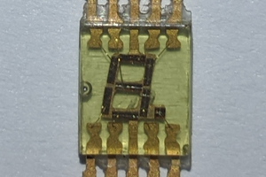
Documentation on the IS32FL3738 chips is pretty terse and this is the first time I have messed with them. In order to figure out how to drive the chips, I used a PC based USB to I2C dongle (TotalPhase Systems Aardvark) and a tool that I wrote that accepts text file input and drives the I2C bus. I roughed out a minimal initialization sequence for one of the driver chips and got fairly close. It took a couple of hours of experimentation to get the first LED to turn on. Then I progressed to controlling multiple rows and columns and getting the green controller operating. The red and green LEDs look yellow when both are lit.
In order to generate the data for actual characters, I wrote a tool in Labview to take LED on/off data from a GUI and output it as a .csv file formatted for the LED ON/OFF registers on the IS32FL3738 chip. Labview is a good tool to generate GUI interfaces quickly for me. The bit manipulation and data handling capabilities adequate for this type of work.
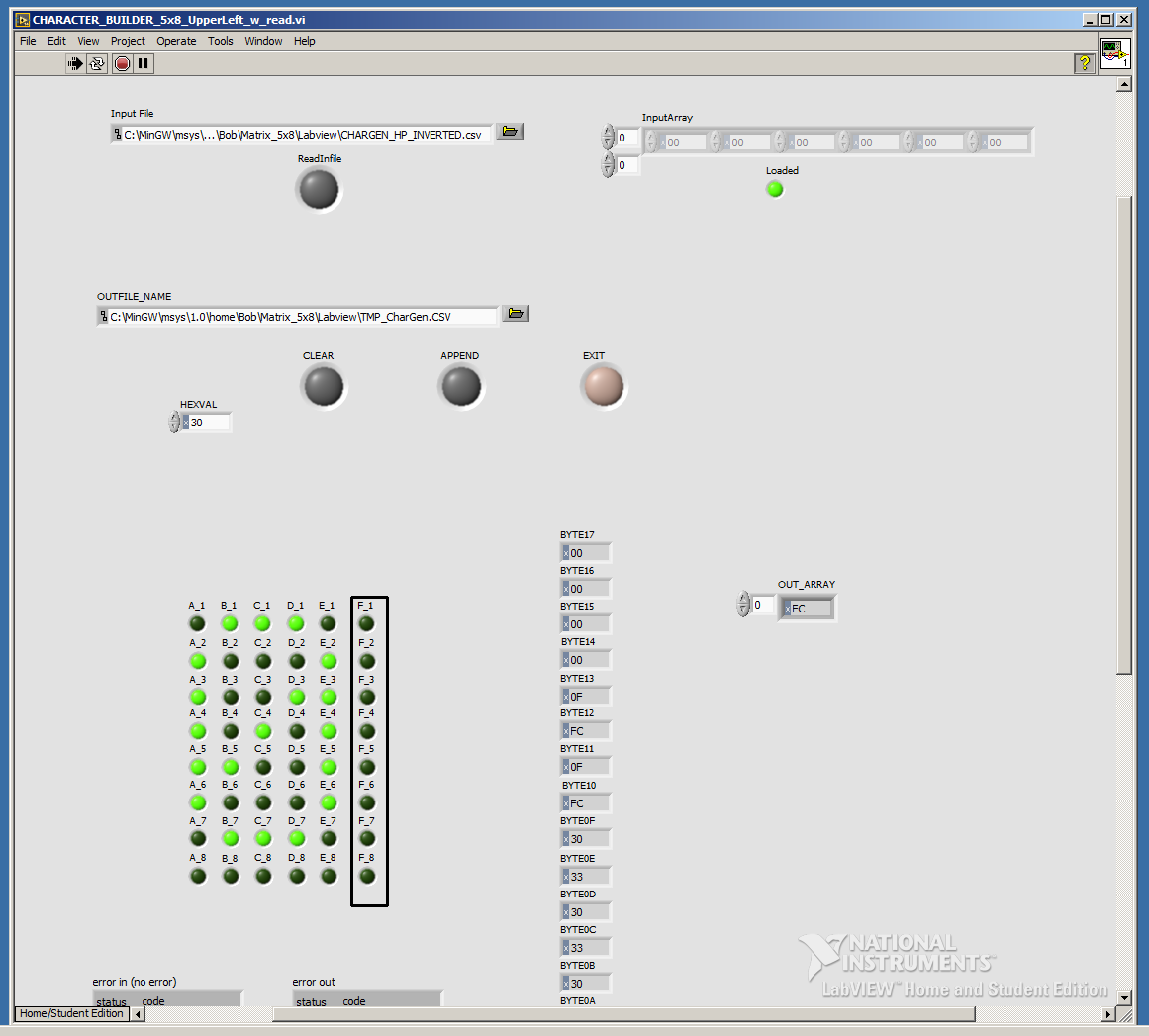
The IS32FL3738 chips support a 6x8 matrix, but I am only using a 5x8 matrix. I included the extra column and data in the output for completeness. The tool supports reading an existing data file for editing. Click on a dot...
Read more »


 Albert Gonzalez
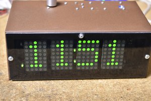
 Robert
Thanks!
I looked at the LTL-7100M data sheet and that is kind of a funny configuration. The IS31FL3730 driver chips could drive quite a few of them if you set the matrix up yourself. At $3 each it would get expensive fast though.
Good Luck!