 Shu Takahashi
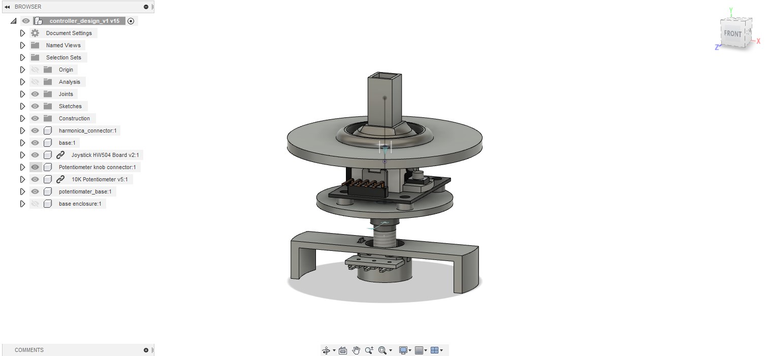
The first part we decided to start designing was the base unit. This part is responsible for providing the joystick movements as well as the MIDI knob (potentiometer) movements.

We decided to work on this first because we were still discussing how the harmonica unit would work. Besides, working on this part was one of our top priorities as this must function flawlessly and hold the harmonica unit steadily. I had an idea of how the joystick module and the potentiometer were going to function together, so I made a quick sketch before creating any models in CAD.
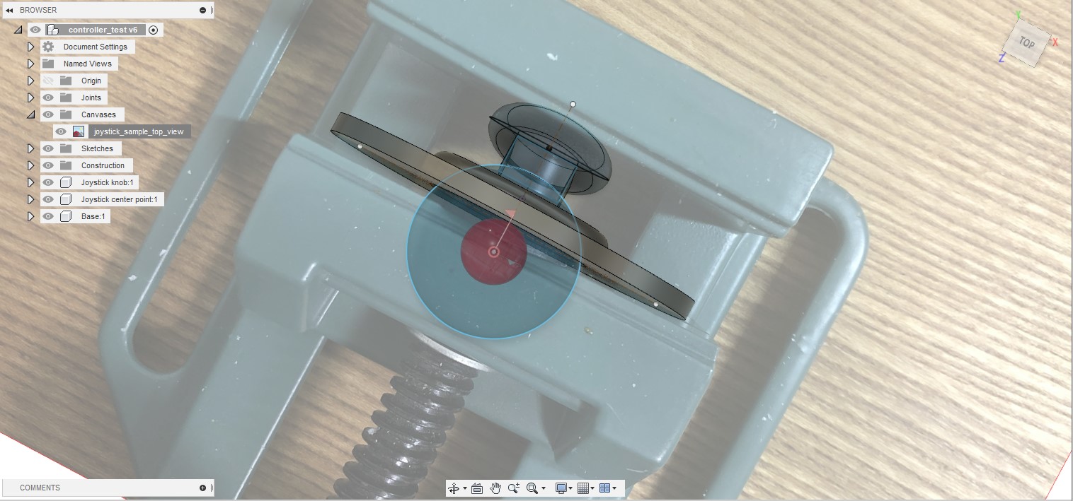
I began by creating simple test designs for the joystick handle part using Fusion 360. I had never 3D printed parts for a joystick before, so I wanted to make sure that I could design this component properly first. I took a picture of the joystick handle that came with the module and made measurements from there. I also added a ball joint and a cover to ensure that the joystick could still move freely.
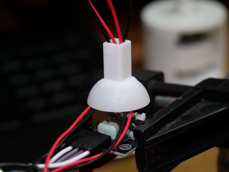
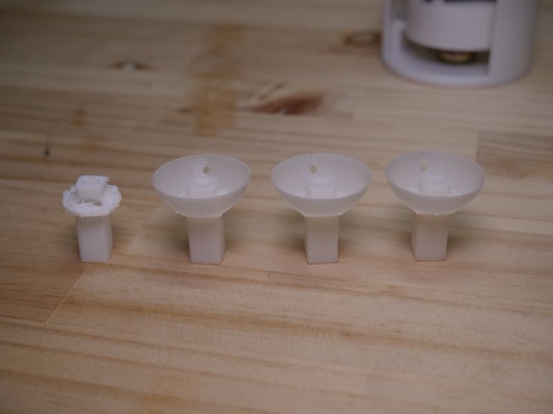
Before moving on to designing the base unit, I also decided to test fit the joystick module and the joystick knob handle to find the appropriate measurements. It’s always difficult to find the right dimensions for the parts to fit together snuggly and this time was no different. Luckily for this test component, only two re-prints were needed.

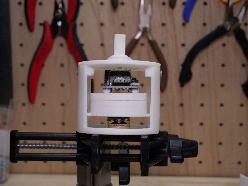
 It took a while to make adjustments, wait for the 3D printers, and to test fit the components; however, all this patience paid off at the end and I was satisfied with the result. The video below is a short demo of the base unit.
All there is left to do for the base unit is to add the enclosure for holding the electronics components that will be located in the base unit. The walls of the base unit still wiggles a little bit, but I hope to resolve this issue in the next prototyping stage.

Discussions
Become a Hackaday.io Member
Create an account to leave a comment. Already have an account? Log In.