 Shu Takahashi
We have been working to prototype the harmonica unit for the past couple of weeks, but we have yet to share this on our log page. However, now that most of the work on the harmonica unit is done, we’re ready to share what we have accomplished so far.
At this stage, the design requirements for the harmonica were very clear. It needed to hold an array of 13 air pressure sensors, hold the multiplexer breakout board, be in the form of a harmonica, and fit together with the base unit. This meant designing both the plastic components as well as a PCB board to hold all the electronics components together.
I first designed the air holes and the PCB to go with it. I used the same dimensions we used when Pato and I experimented with the air pressure sensor a few days ago. Designing the PCB and the air pathway component to fit together was really challenging because it required a close coordination between my CAD program, Fusion 360 and my EDA program EAGLE. I initially tried to do everything in Fusion 360 with the new update that integrated EAGLE; however, I had problems with routing and exporting at a later stage, so I used two separate programs.

Printing the air pathway component was straight forward. Although the back part of the component warped a little bit because I used ABS plastic. Fabricating the circuit board was a little bit more challenging. To begin with, this was my first time milling my own PCB using a CNC machine. Learning the process for operating the CNC machine was quite a bit of a learning curve. Also, I unintentionally designed the PCB from the bottom side. This resulted in a PCB layout that was mirrored horizontally. Luckily this problem was resolved by flipping the export image horizontally, but the whole process took about three days, which delayed this project by a few days.

In the circuit board, I also included a transistor switching circuit to control the vibrational motor from the Arduino. The first circuit board had errors, but the second attempt was a success. I was able to place all the required electronic components in the harmonica unit into a one nice PCB.
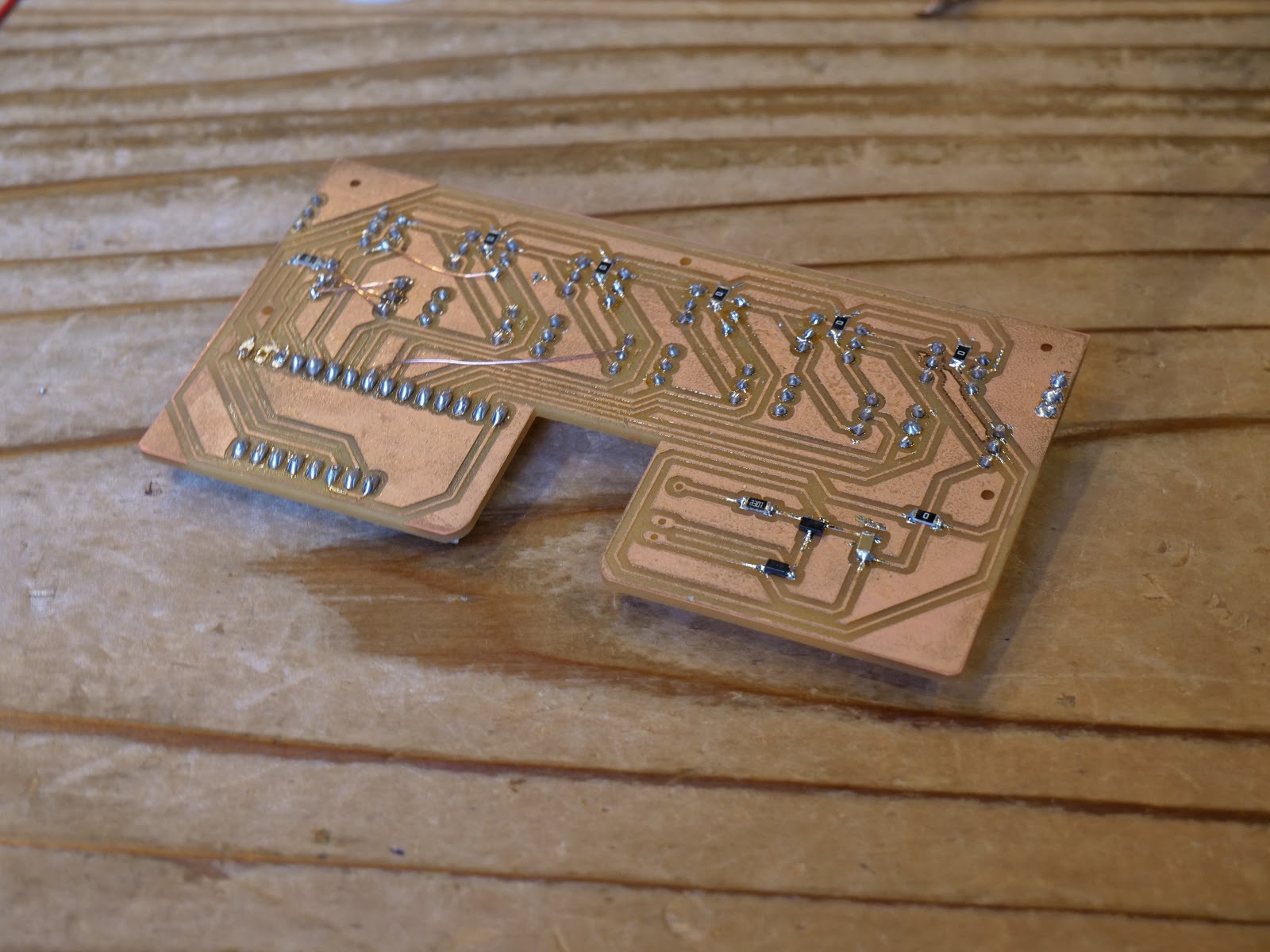
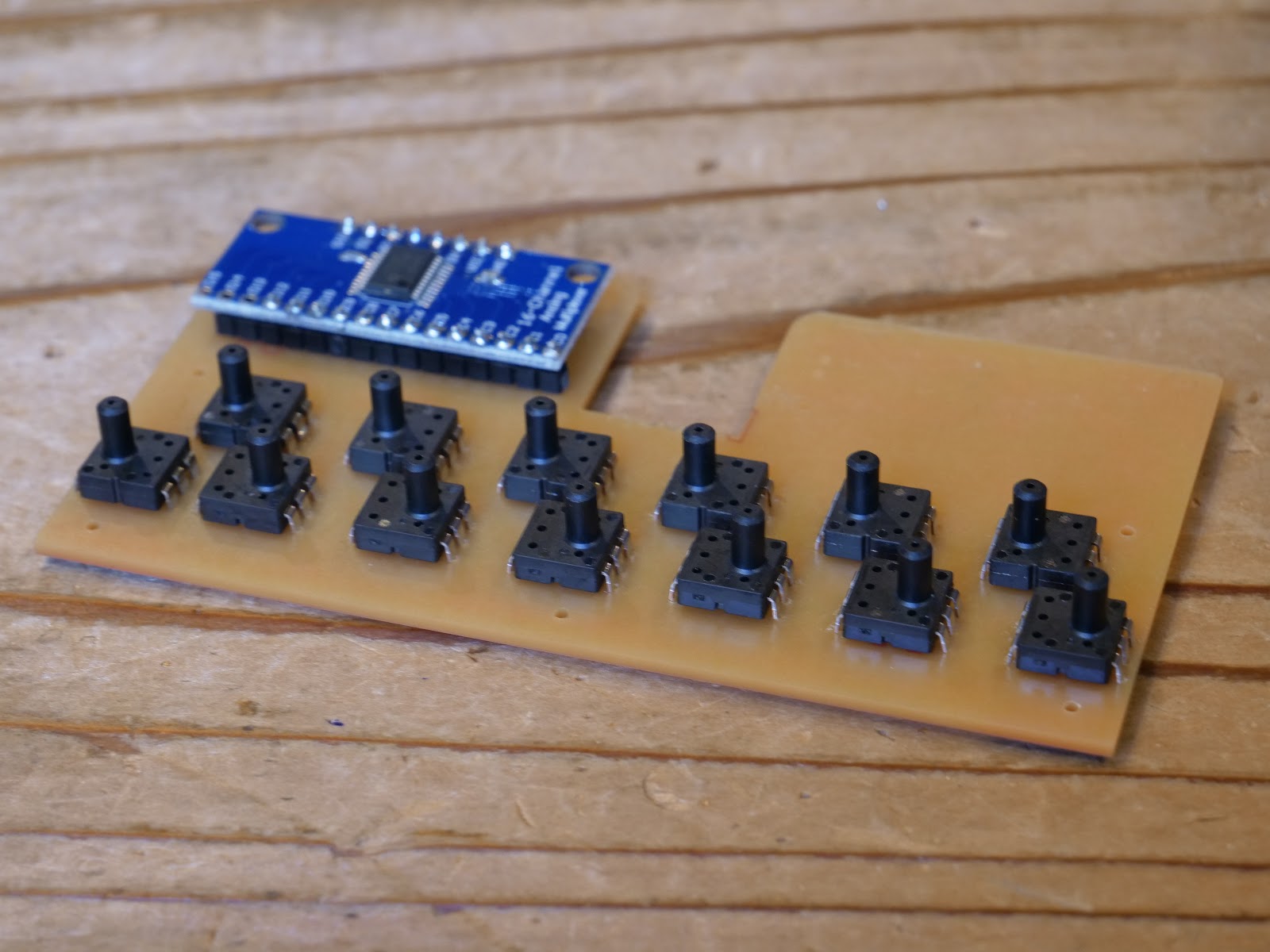
The circuit board and the air pathway plastic component fit together well on the first try which was a bit of a satisfying moment. In the air pathway component, I made a small tunnel to route the wires through so that it can access the Arduino Leonardo in the base unit.

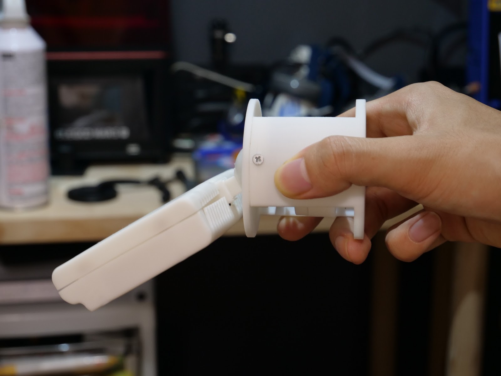
Now all there was to design for the harmonica unit was a nice enclosure to hide all the electronic components and the air pathway component. Designing the enclosure required a bit of thinking and quite a lot of time as well. First, I wasn’t sure how the enclosure should fit together. I initially thought of making the enclosure like a sleeve, but this was not possible because we were still at a prototyping stage and so the electronics needed to be easily accessible in case something went wrong. At the end, I designed a two part enclosure that covered the components from the top and the bottom. I designed the two enclosure components to be held together using a nut and a bolt. I put an effort into hiding the screws from the top side to make the enclosure look nice.
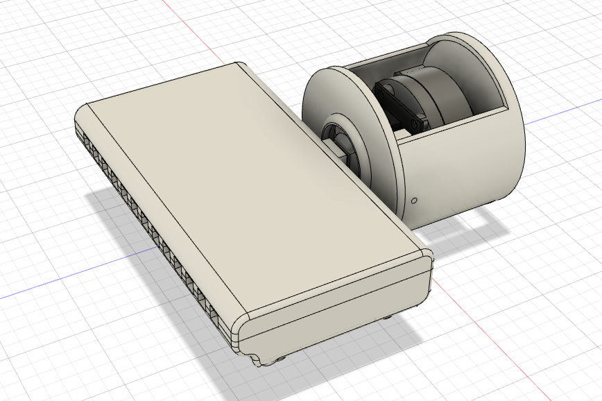
Printing the bottom and the top enclosure took a very very long time. This is partly because I chose to use an SLA printer as the two enclosure components had some complicated geometries that could be damaged from typical FDM supports. But the wait was worth it. Although there were some warps in the final print, it still looked very similar to what I designed in CAD.
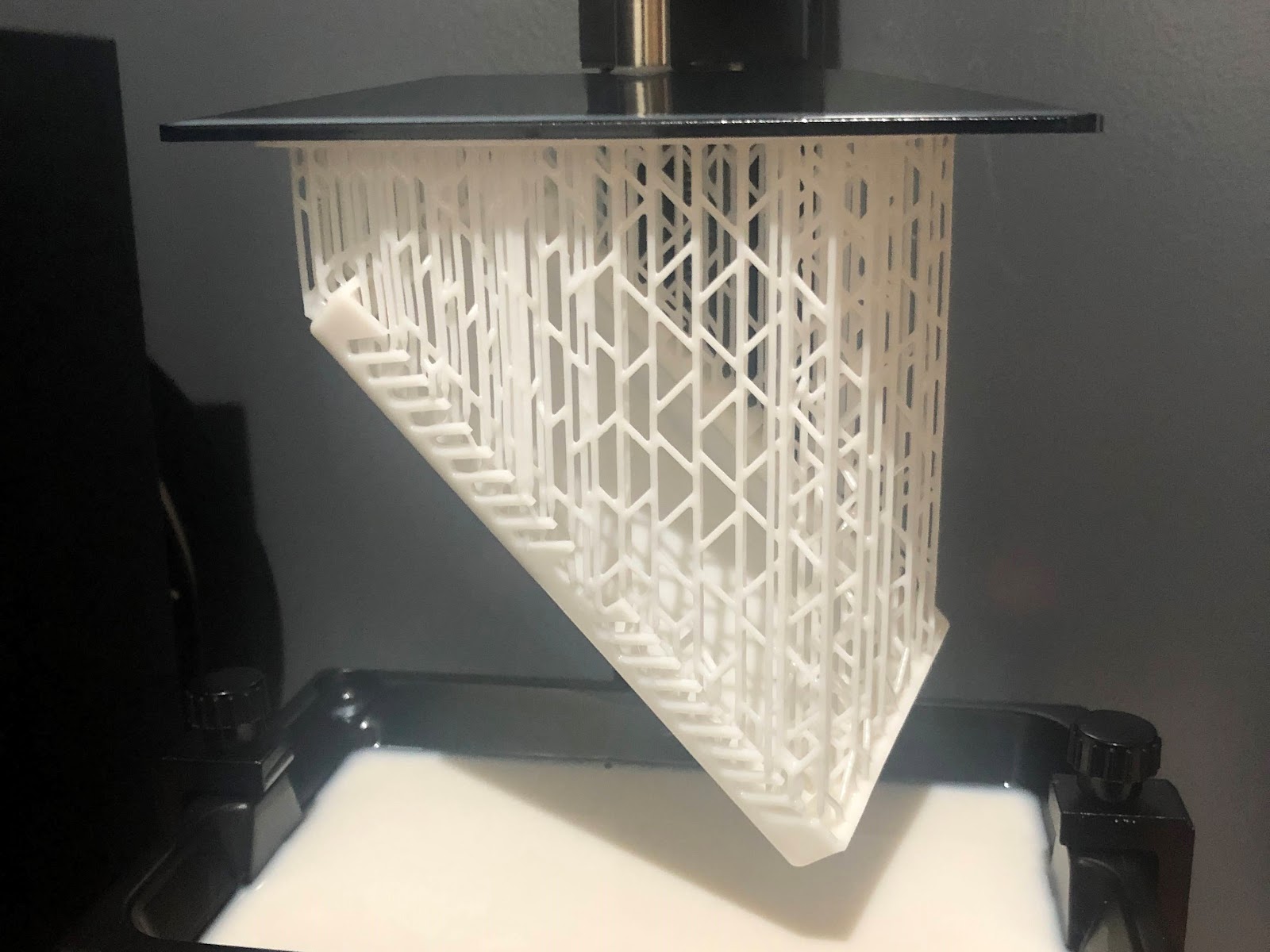
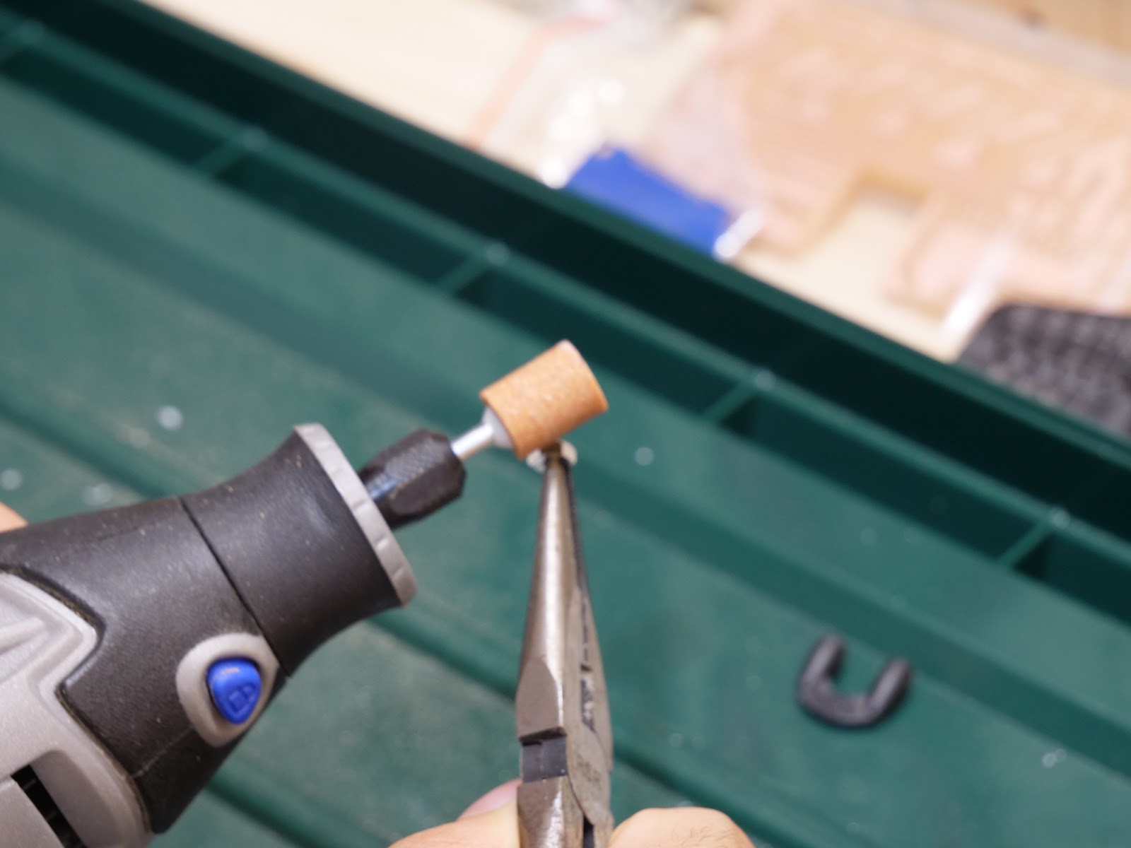
Although the prints looked great, it still needed some post processing. I filed the sides that had the supports to get a smoother surface. The pockets I designed in the top enclosure to fit the nuts came out too small. Instead of trying to reach in and remove the excess material inside the pockets, I grinded the nuts so that it can fit inside.

Everything was coming together nicely. But that was until I tried assembling the harmonica unit and the base unit together. It turned out that the harmonica unit was too heavy to be supported only by the springs inside the joystick unit.
With the deadline I set for myself approaching, my mind panicked and I wasn’t sure what to do. Fortunately, when I went to my loca makerspace, Fablab on the next day, one of the members came up with a simple yet brilliant solution to use a rubber band to add extra support. Although I don’t have a picture of this, it worked like a charm. For now, for the first prototype I will be using this solution. In the future prototype, I’m thinking of either making the harmonica unit lighter or designing a mechanical system to support the weight of the harmonica unit.
Discussions
Become a Hackaday.io Member
Create an account to leave a comment. Already have an account? Log In.