 Shu Takahashi
Choosing Electronic Components
Having chosen the air pressure sensor, there were still many electronic components to select and test. Most notably, the microcontroller and the joystick sensor.
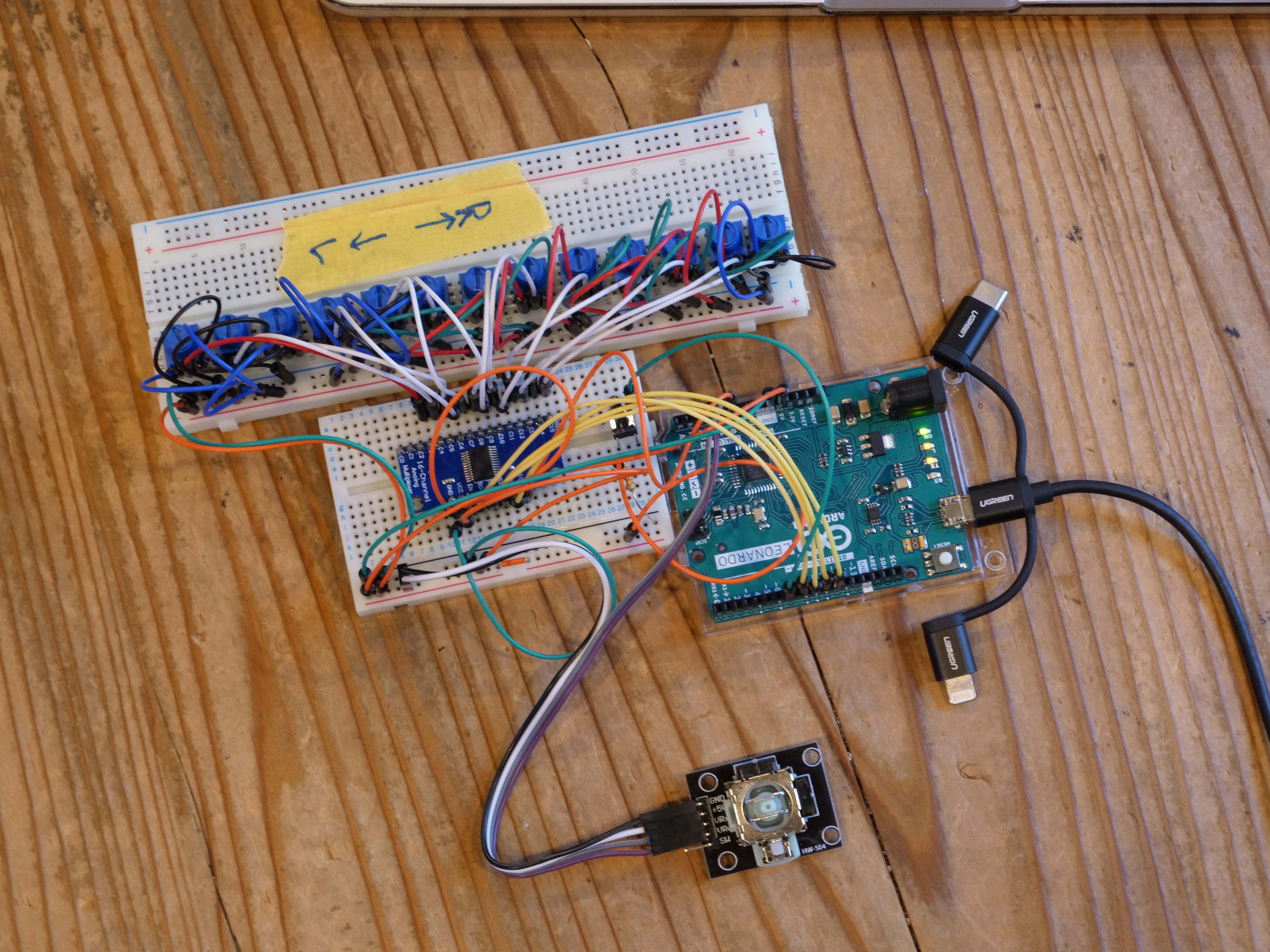
For the microcontroller, I initially wanted to choose something with plenty of memory space and options for wireless connectivity such as the ESP32. However, as I was testing out the mouse library with my Arduino UNO, I realized that most boards I’ve used in my past projects do not support it. I found out that to use the native mouse and keyboard library, the microcontroller had to be 32u based. This narrowed down my options significantly. With the limited time I had left to order and wait for parts to arrive, my best option was to use the Arduino Leonardo. This board doesn’t have any wireless options built-in nor much memory space compared to boards like the ESP32, but it’s suffice for the first proof of concept prototype.
Arduino Leonardo has 12 analog input pins. However, for this project I will need a total of 16 analog pins. 13 from the pressure sensors, two from the joystick unit and one from the potentiometer. The first intuitive solution I had in my head was to use a multiplexer. Without much thinking, I ordered a breakout board for a multiplexer IC CD74HC4067 from Texas Instruments. When the breakout board arrived and I thought about how the program would work, I realized that I would not be able to program an external interrupt. There may be a work around to address this oversight such as using a scheduled interrupt, but for now, my option will be limited to polling. This may limit the features and performance of the output programs (i.e. MIDI or USB Mouse), but it will be enough for the first proof of concept prototype.
Choosing the joystick sensor was relatively straightforward. As Pato and I discussed in our CTQ, we wanted to make this device as accessible and affordable as possible. For this reason, we decided to use the joystick unit from a Xbox 360 controller. These joystick units can be bought in many countries around the world as a replacement part. Just for making the prototyping process easier, I also bought a joystick unit that came with a breakout board from a company called HiLetgo. This joystick unit also seemed to be very popular as I could find the identical product on Amazon in the US, Mexico and Japan. Coincidently, when I compared these two modules, the joystick was identical. So for now, I decided to use the Joystick module from HiLetgo because it already had a breakout board attached. In the later prototyping stages, I will be able to design a PCB for the Xbox joystick, so that it can also be used to build the device.
Testing the Joystick Mouse
To make sure that the joystick module and the Arduino Leonardo I ordered worked together, I ran the example code from the official Arduino documentation. The program worked as expected and I was able to control my computer mouse using the joystick module. It’s not too clear yet how this program will work in conjunction with everything else the processor needs to process, but hopefully I will figure it out in the coming days.
Testing the Multiplexer
The multiplexer board will be connected to the 13 air pressure sensors. It will essentially act as a rotary switch to choose which channel to connect the Arduino to. The Arduino with the multiplexer will be constantly switching between the 13 channels and writing the results to an array.
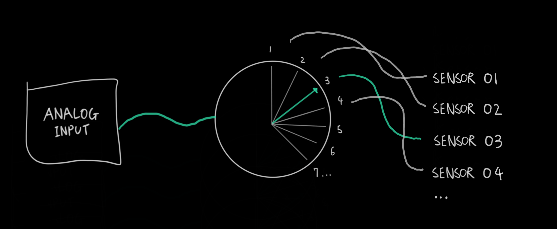
This array can then be used by the program to take specific actions based on the sensor values. At this stage, my goal was to make sure that the multiplexer could be used to switch between the 13 channels and have the data recorded on to an integer array.
Which channel to connect to is controlled using four digital pins that receive the channel number in binary. For example writing LOW, LOW, LOW, HIGH to the four pins will connect the Arduino’s analog pin to channel number one on the multiplexer. For each air pressure sensor, the Arduino will output the channel number in binary, take an analog reading from the sensor via the multiplexer, and record this reading on to an integer array. The code below executes exactly that.
In the function readMux, the Arduino uses digital pins 8, 9, 10 and 11 to select the channel on the multiplexer. It then takes an analog reading from analog pin 0 and returns this value. In the main loop program, the Arduino then iterates through the 13 channels and writes the results to an int array named pressure_sensor.
//Mux control pins
int s0 = 8;
int s1 = 9;
int s2 = 10;
int s3 = 11;

//Mux in signal pin
int SIG_pin = 0;

//sensor value table
int pressure_sensor[13];

void setup() {
  // put your setup code here, to run once:
  pinMode(s0, OUTPUT);
  pinMode(s1, OUTPUT);
  pinMode(s2, OUTPUT);
  pinMode(s3, OUTPUT);

  //initialize control pins
  digitalWrite(s0, LOW);
  digitalWrite(s1, LOW);
  digitalWrite(s2, LOW);
  digitalWrite(s3, LOW);

  Serial.begin(9600);


}

void loop() {
  // put your main code here, to run repeatedly:
  //read through channels 0 to 12
  for(int i = 0; i < 13; i++){
    int sensor_value = readMux(i);
    Serial.print("Channel: ");
    Serial.print(i);
    Serial.print(" Value: ");
    Serial.print(sensor_value);
    Serial.print("\n");
    pressure_sensor[i] = sensor_value;
    delay(1);
  }

  for(int i = 0; i < 13; i++){
    Serial.print(pressure_sensor[i]);
    Serial.print("\n");
  }

  delay(5000);


}

int readMux(int channel){
  int controlPin[] = {s0, s1, s2, s3};

  int muxChannel[13][4]{
    {1,1,0,0}, //channel 3
    {0,0,1,0}, //channel 4
    {1,0,1,0}, //channel 5
    {0,1,1,0}, //channel 6
    {1,1,1,0}, //channel 7
    {0,0,0,1}, //channel 8
    {1,0,0,1}, //channel 9
    {0,1,0,1}, //channel 10
    {1,1,0,1}, //channel 11
    {0,0,1,1}, //channel 12
    {1,0,1,1}, //channel 13
    {0,1,1,1}, //channel 14
    {1,1,1,1}  //channel 15
  };

  //loop through the 4 signal pins
  for(int i = 0; i < 4; i++){
    digitalWrite(controlPin[i], muxChannel[channel][i]);
  }

  //read the value at the signal pin
  int val = analogRead(SIG_pin);

  //return the reading value
  return val;

}
Discussions
Become a Hackaday.io Member
Create an account to leave a comment. Already have an account? Log In.