 Angkan Gayen
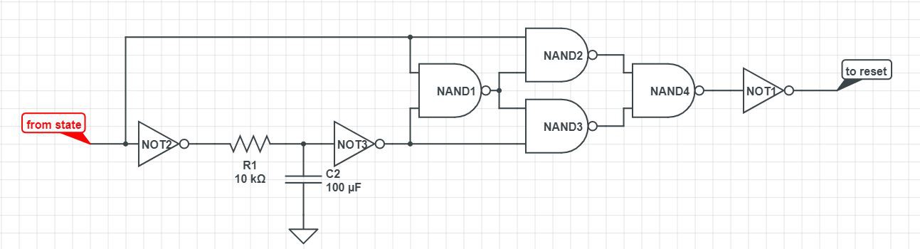
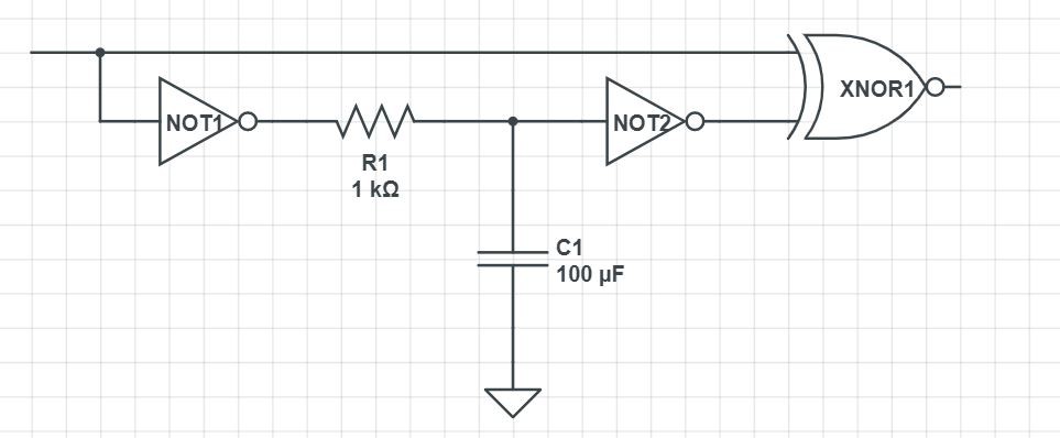
The program data is send over Bluetooth HC-05 , whenever there is data available the state pin of HC-05 goes LOW. at that moment the Arduino's reset pin also has to be LOW for a short period of time so that the Arduino can go into programming mode.
0%
0%
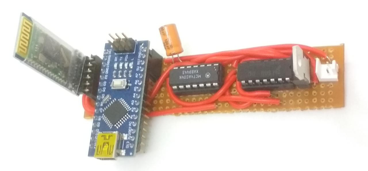
programming Arduino Nano through Bluetooth
ota
Become a Hackaday.io member
Already have an account? Log in.
Just one more thing
To make the experience fit your profile, pick a username and tell us what interests you.
Pick an awesome username
hackaday.io/
Your profile's URL: hackaday.io/username. Max 25 alphanumeric characters.
Pick a few interests
Projects that share your interests
People that share your interests
 press and hold this button at the time of powering up that puts the HC-05 to AT command mode.
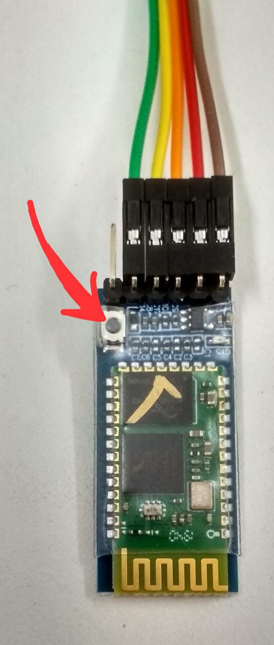
 Embedotronics
 Maria Carlina Hernandez
 Make&Play
 Gintaras Valatka