I recently got a FOMU FPGA board and I couldn't wait to tinker with it! :D
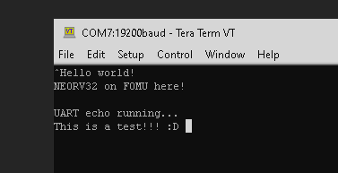
I have build a very simple setup consisting of a minimal NEORV32 SoC, a USB-UART bridge IP and some FIFOs. The result is a FOMU setup that blinks a heart beat on the RGB LED and echos all incoming UART data back to the host - all controlled by a RISC-V core.
If you are curious check out this GitHub discussion for more information (including the setup's sources).
After some struggles (and nightmares!) understanding the IEEE-754 specs and several FPU IP data sheets I have nearly finished implementing the NEORV32 floating point extension.
I have decided to implement the RISC-V Zfinx floating-point extension rather than the standard F extension to focus on size-optimization. Zfinx uses the standard integer register file x instead of a dedicated floating-point register file f, which is required by the F extension.
---------- more ----------
Using the x registers for floating-point operations makes context save/restore much faster since there is no need to push/pop f on the stack and also lowers hardware requirements by avoiding another full-scale 32*32-bit register file.
As a nice add-on the following F floating-point instructions are obsolete when using the Zfinx:
FLW, FSW - load/store f registers
FMV.X.W, FMV.W.X - move data between f and x register files
Unfortunately, Zfinx is not not yet supported by the upstreamRISC-V gcc port. There are experimental patches but I like having a production ready setup, which allows "plug-and-play" - or download-and-play, to be more precisely.
Therefore, I decided to use a plain rv32i toolchain and add Zfinx support by adding an intrinsic library. In case you don't know, intrinsics are basically some kind of inline assembly nicely wrapped up in C-language functions. I have written a set of macros (see on GitHub) that finally generate inline assembly producing a 32-bit instruction word using the ".word" assembler directive:
asmvolatile (".word 0x1234abcd");
In this case, there would be a static instruction word 0x1234abcd. With some help of the macros you can modify the instruction word - or to be more specific: Modify things like opcode and register addresses making it a "custom instruction" macro.
Putting it all together, the Zfinx intrinsic library looks like this (cut-out of the floating-point addition instruction FADD):
This function uses the noinline attribute forcing the compiler to turn it into a real function, that is called using the machine's calling convention. This calling definitions define the registers a0 and a1 to be used for passing the actual arguments. The function's result is also returned in a0. These two registers are hardcoded into the FADD instruction.
Here is a cut-out of the RISC-V Insruction Set Manual showing the encoding of the FADD instruction to see how the instruction is constructed. Do you see the resemblance? ;)
There is also a dummy integer ADD instruction, which adds the function's arguments, but discards the results as it is written to register x0 that is hardwired to zero in RISC-V. This is a nice work-around to avoid that the compiler might optimize the function into some sort of constant propagating simplification. It CANNOT optimize the function to be some sort of constant propagating thing as we are actually doing something with the arguments that the compiler can identify (using ADD).
This intrinsic library works pretty well. I have also added "emulation" functions that compute the same operations as their intrinsic counterparts but using the GCC builtin functions. For example the according FADD emulation function looks like this:
So its a plain C-language floating-point addition. Since everything is compiled for a rv32i architecture, the compiler infer its builtin functions to compute the floating-point addition, which is a great reference to check the results from the actual hardware floating-point unit against.
I have setup tests for all Zfinx instructions that compare the results against the "golden" software-only reference. The inputs are generated by a XOR32 pseudo-random number generator and every now and then special values like INFINITY or NAN are inserted. Everything is running on one of my FPGA boards (since several hours) and the results look quite promising :D
<<< Zfinx extension test >>>
SILENT_MODE enabled (only showing actual errors)
Test cases per instruction: 50000000


#0: FCVT.S.WU (unsigned integer to float)...
Errors: 0/50000000 [ok]

#1: FCVT.S.W (signed integer to float)...
Errors: 0/50000000 [ok]

#2: FCVT.WU.S (float to unsigned integer)...
Errors: 0/50000000 [ok]

#3: FCVT.W.S (float to signed integer)...
Errors: 0/50000000 [ok]

#4: FADD.S (addition)...
Errors: 0/50000000 [ok]
I have not yet published the FPU VHDL code on the NEORV32 GitHub repo. There are still some tiny things to fix in the FPU. Most important: code clean-up (also,the VHDL sources are still full of inappropriate curse words... xD).
Also, I have not found a convenient way to verify the generated exception flags. The standard C++ handling of the exceptions generated by the SOFTWARE floating-point emulations seems to be not supported by my toolchain.
#include<fenv.h>#pragma STDC FENV_ACCESS ON
Maybe someone out there has a nice idea how to verify the exceptions?! ;)
The FPU sources will be released within the next days - so stay tuned!
The cool thing of having a soft-core processor is you can add exactly the features you are wishing for. Some days ago I got a hint on the WS2812 LEDs, which are used in Adafruit's awesome NeoPixels. The interface is quite heavy when it comes to timing constraints and I figured out that some platforms struggle with it.
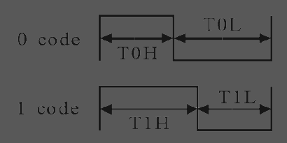
WS2812 Protocol
In summary, the WS2812 interface is based on a single signal carrying an asynchronous data protocol. It uses a fixed 800KHz frequency and modifies the duty cycle to carry the '0' and '1' bits.
Small mikrocontrollers like AVRs can tackle the hard timing (for example using the FastLED library), but might need some inline assembly to keep up with it. Also, the image is better off being stored entirely somewhere in memory (consuming precious RAM) since real time rendering might crash in-time bit-banging. Things are getting even more complicated when pairing the hard timing constraints with setups using interrupts...
More powerful platforms like the Raspberry PI do have the processing power to bit-bang the interface, but they also might run into real-time problems when OS interrupts kick in.
In summary, pure-software based approaches come with more than just a few issues. So, why not create a dedicated hardware interface that takes all the critical interface work from us?
---------- more ----------
The NEORV32 Custom Functions Subsystem
To implement a native WS2812 interface I am using the Custom Functions Subsystem (CFS) of the NEORV32 RISC-V Processor. This subsystem provides a blank template for creating application-specific memory-mapped accelerators and interfaces. Besides the actual processor interface, the CFS features "empty" IO conduits allowing easy integration of external signals.
The CFS also provides 8 different "clocks" derived from the system's main clock:
May version of the interface uses two memory-mapped registers: The control register and the data register. The control register is used to configure everything. Writing data to the data register will trigger a new transmission to the LED stripes.
For the WS2812 interface core I have implemented a programmable clock divider (selecting one of the clocks mentioned above), a shift register for serializing LED data and a programmable counter with two programmable comparators. Everything is orchestrated by a simple state machine.
The counter is used to count the ticks of the selected clock and defines the base bit rate. The first programmable comparator is used to configure the time of the whole period ("T_total" = 1.25µs) for sending a single bit. The second comparator selects one out of two programmed times for setting the LED data line high. Hence, it is used to define the high-time for sending a '0' or '1' bit according the current bit of the data shift register. The serial output can be multiplexed to 4 different channels, which allows to drive up to 4 independent NeoPixel stripes in parallel - or to send "broadcast data" to all of them at once.
The shift register can be configured for 24-bit data (for the "normal" RGB LEDs) and also for 32-bit (for the RGBW LEDs that provide an additional white LED chip). All configuration is programmable so it can be modified by the software at any time. This allows to use RGB and RGBW LEDs at the same time. The interface can also support the WS2811 LEDs by adapting the timing configuration (but I have not tested that yet).
The whole interface module takes up only 140 LUTs and 100 FFs on an Altera Cyclone IV FPGA and has no problems integrating into a 100MHz system.
The Result
I setup the NEORV32 + WS2812 CFS on a Terasic DE0-nano FPGA board and connected two NeoPixel arrays: An Adafruit 12-LED RGB ring to channel 0 and an Adafruit 8-LED RGBW stick to channel 1. Since the NeoPixels are powered by a 5V supply I am using a random 74HC04 hex inverter (two inverters in a row, of course) as simple level shifter to connect to the 3.3V FPGA IOs (placed on the second breadboard).
The animations are quite simple, but right now this is more like a proof-of-concept. Oh, and please note that this "video" is just a chopped GIF ;)
LED data is send to the stripes by the send_data function, which configures the interface for the actual mode (24-bit or 32-bit) and enables the selected channels:
voidsend_data(uint32_t channel, uint32_t mode, uint32_t data){
uint32_t channel_int = channel & 3; // new channel selectuint32_t mode_int = mode & 1; // RGB (24-bit) or RGBW (32-bit) modewhile(WS2812_CONTROL & (1 << WS2812_CT_BUSY)); // polling (FIXME!): wait for busy flag to clearuint32_t ctrl = WS2812_CONTROL;
ctrl &= ~(0b1111 << WS2812_CT_CHMASK); // clear current channel selection
ctrl &= ~(0b1 << WS2812_CT_MODE); // clear current mode
ctrl |= (0b1 << (channel_int + WS2812_CT_CHMASK)); // set new channel enable
ctrl |= (mode_int << WS2812_CT_MODE); // set new mode
WS2812_CONTROL = ctrl;
WS2812_DATA = data; // send new LED data
}
As already mentioned, the whole setup runs at 100MHz. Sending data to a RGB LED (24-bit) takes (1.25µs * 24) / 10ns = 3000 clock cycles for transmission. Sending data to a RGBW LED (32-bit) takes (1.25µs * 32) / 10ns = 4000 clock cycles for transmission. Since the transmission is entirely handled by the hardware, the CPU has enough time (up to 1500 or 2000 instructions, respectively) to take care of other things - like computing the next image frame.
Source Code
The VHDL and C source files are available on GitHub as Gists:
In the next step I would like to add interrupt support to avoid nasty polling and maybe some kind of data buffer (maybe a FIFO or maybe just some simple double-buffering).
I am also thinking about adding the WS2812 hardware interface as a standard (but still optional)module to the NEORV32 SoC. Indeed, this is quite a niche application but somehow NeoPixels really put me under their spell - they are such a great thing to play with. And hey, they are called NEOPixels - so how could I resist? :)