 Charlie Smith
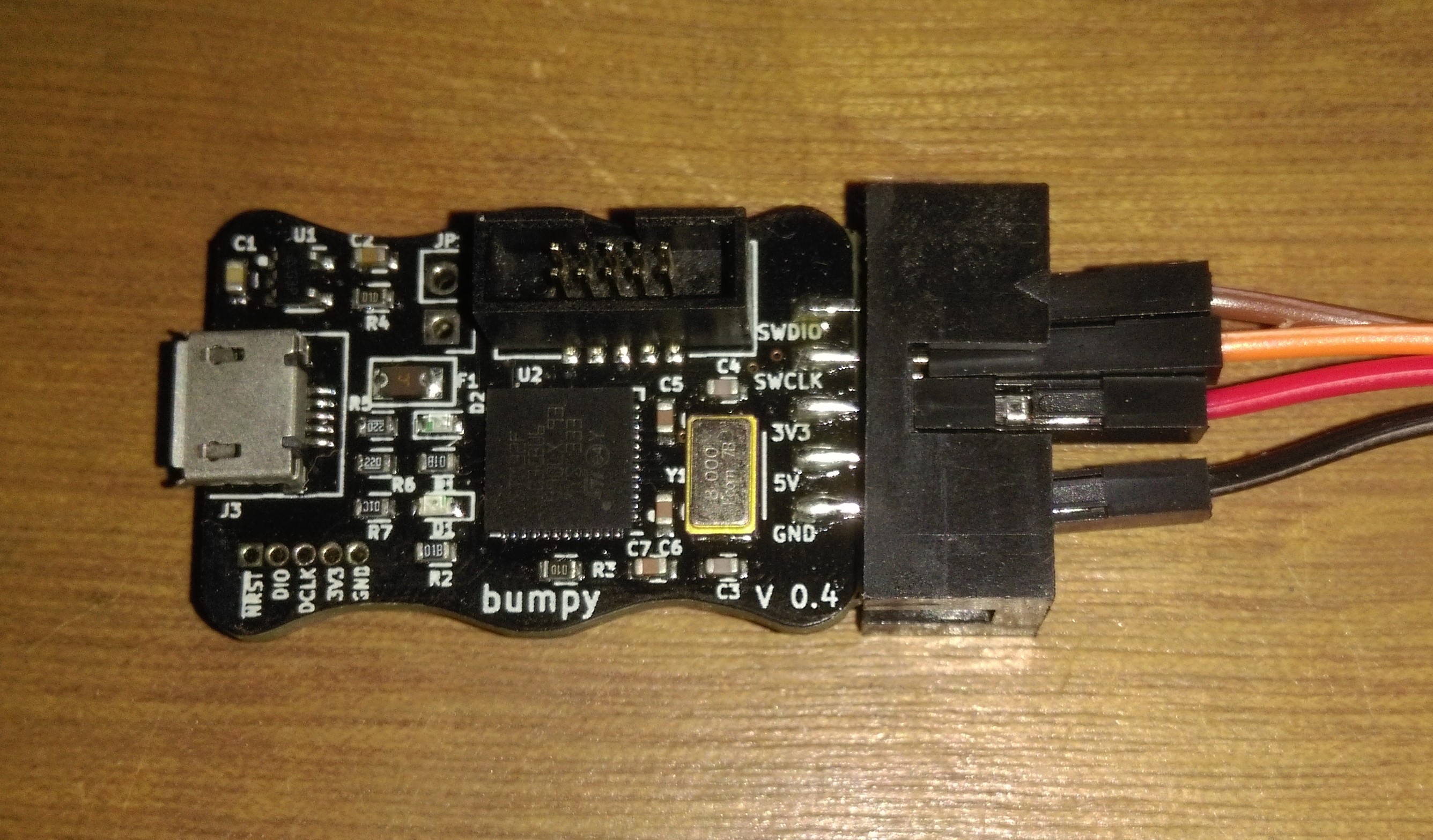
In the previous log I build one of the radio boards and attempted to program it, running into difficulties about not having a programmer capable enough. I also mentioned about a new programmer called a Bumpy which has been designed to program nRF52 SoCs, specifically the nRF52832. As a reminder I'm using the nRF52833, a fairly similar chip, so it would seem that this programmer should work no problem. Well, as you may be able to guess, things are never quite that easy. The programmer firstly took quite a while to show up, coming from the US to the UK, but at least when I plugged it in everything seemed to be working. I would like to just include a picture of it here as I really like the look of the thing, I need to design more of my boards with interesting outlines:
 But this is where I ran into issues, as before I'm using Black magic firmware with GDB to program over SWD, previously only a generic Arm Cortex-M device showed up in GDB. With the new programmer, I still had this device, but also had one labelled as "Nordic nRF52 Access Port". With some playing around trying to use each of these devices, I still couldn't get something to program such that the "compare-sections" command would validate that the memory was correct.
Eventually I discovered that this was down to the firmware of the Bumpy, and with some further digging through the source code discovered that in the nrf51.c file there is a method called "nrf51_probe". This gets called to check if a connected device is some valid Nordic MCU. However, in the Bumpy version of the firmware this is done by reading a device specific value from the MCUs memory to check against a list of known IDs to discover what the device is. Unfortunately, the nRF52833 is a fairly new chip, especially in the QFN40 package I am using. As such, the code for my chip is not in the list and so my board is not recognised as a Nordic device. While I was able to read this value from my chips memory, this isn't really the best solution to checking a particular device. One main reason why is that part of the check is so that the correct amount of memory can be assigned when setting up programming. However, the information for this is directly readable from the chip, so there is no need to use a reference table. What is more, the current up to date version of Black Magic does allow for any current and future Nordic SoCs to be programmed, buy checking if the device is in the nRF51 or nRF52 family before reading the memory sizes from the device. As I needed to reprogram the firmware on my Bumpy anyway, I thought it was probably best to use the more general form of the method in case I use any other chips. This was fairly simple, only having a slight issue of using dfu-util to update the firmware. From Linux the programmer wasn't recognised, while on Windows it claimed to successfully program it, but without actually programming it (which resulted in quite a lot of confusion as no change seemed to apply). Eventually I discovered I needed to use dfu-util with sudo permissions on Linux for the programmer to show up, and then everything just worked.
Toolchain
So having waited a month for the programmer to show up and probably another week just being able to use it I can finally get started. Well yes and no, before starting this project, I had only ever programmed things via the Arduino IDE. So it was quite a leap to be able to even set up the toolchain. This wasn't helped by wanting to do everything on Windows (as I only have Linux installed on a laptop and don't want to use that for everything). I found something called MinGW installed make, GDB and the compilers I need grabbed a copy of the Nordic SDK and managed to get everything set up. While I didn't really know how to use make files (and still don't fully), Nordic provided some really good templates and with only some small changes so I could setup project directories in a way I like I was able to compile a program. While I had been able to do this before (Linux makes things much easier), at the time I was still unable to program my board and so couldn't test the build. Thus I now went straight into the next metaphorical brick wall.
Blink
The first program you should run on any MCU is blink. I think getting an LED flashing just clearly shows that at least something in the MCU is working. However, no matter how I played around with my code (I wasn't quite sure I was using the correct pin numbers) the bi-colour LED on the board refused to change. Poking around with a multi-meter I found that other pins would work, but not my LED pins. After some amount of time I discovered found that the reason for this is that I had hooked my LED up to the NFC pins. While these can be used as GPIO, it seems that they can't by default (even if this seems a little odd). The solution is to add the compiler define "CONFIG_NFCT_PINS_AS_GPIOS" and at last I have blink. In fixing this I also found there is a define "CONFIG_GPIO_AS_PIN_RESET", so for the reset pin you have to enable it for the alternate function, whereas the NFC you have to disable the less general function. Anyway, this was a lucky find and meant I didn't spend far too long trying to get the reset button to work. I also want to make a comment that putting a breakpoint at the start of your program will cause it to stop at that point, even if you are running the device without the debugger. It took me more time than it should have done to work out why my program wouldn't run without the debugger (somehow I was forgetting that I had to tell the device to continue the code each time I ran it with the debugger).
USB
Next on the list of parts to get working was USB. While I do have a fancy debugger/programmer, I quite like having debug messages and other assorted data sent via a USB to a serial port. This was yet another wild ride of hitting my head against a metaphorical brick wall. Nordic has quite a number of examples, however quite a few of these attempt to do everything you could possibly do in relation to what the example is for. As such they tend to have a lot more code than is strictly needed for a basic implementation (one reason most Arduino based examples are much better, as they often only have the code you need). As such it was somewhat difficult to work out what code I needed and what I didn't. When I finally thought I had it all working and could compile and clash my board, I ran into every programmers all time favourite, a segmentation fault. Now this is where things got a bit messy. GDB has a was reporting the error in a section of code which, as far as I could tell, was not being run. From researching this a bit I discovered the compiler optimisation flags where set high enough to make this sort of debugging not work properly. Reducing the optimisation level a bit at least made it so the segmentation fault wasn't in code not being run, instead it was at location 0x0. This didn't really seem much better. Additionally GDBs backtrace command failed to provide anything of use, and complained a lot about not recognising Arm as a valid architecture. With yet more time wasted getting confused about this I eventually found where I had gone wrong... MinGW has a version of GDB for debugging programs running on a full computer, not a MCU. After attempting to make my own build which supported Arm, and trying another toolchain, I eventually discovered one called CodeSourcery which worked (although it still had its own issues). And finally I had a version of GDB which supported what I was doing with it. The backtrace command worked, and showed that the segmentation fault was happening in an interrupt method relating to the clock. After digging around a bit more I found that the important part of the USB examples I had missed where to actually initialise the clock. After that I was able to write data over USB.
Logging
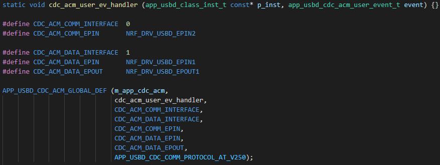
The Nordic SDK has a logging system built in. By calling NRF_LOG_INFO (or WARNING or ERROR) you can very easily send a debug message via a connected debugger. This can be done with either UART or RTT using pre-made logging backends. But I still like my USB, and wanted to get logging working over USB. Unfortunately, there is no USB logging backend. Fortunately, there is a very simple structure to how backends are programmed (and I could mostly copy bits from elsewhere). As such I got it all working rather easily. Starting from the UART backend, and renaming everything. Most code can just be removed, but you still need to be able to write data. Taking just the main parts of the code (VSCode is upset with int types for some reason):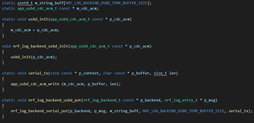
Radio
With that done the only other system which I needed to test was the radio. While previous parts have taken much longer to get working, this is by far the scariest to debug. I have none of the proper tools required to even look at what packets are being sent, let along analyse the performance of my RF traces and antennas (does anyone have any suggestions on a cheap but functional network analyser, or one seeking a new home). Originally I was going to try using a nRF24L01+ as a Rx/Tx which I know works. However, I found it a bit difficult working out how to get the same settings on both the nRF24 and the nRF52, so in the end I decided it was finally time to build a second of radio board and use that. The Nordic SDK has a fairly simple Rx/Tx test example for the radio, requiring only small modifications to work with my board (and to add the USB logging). Soldering together another board wasn't too difficult for the most part, and certainly a lot easier the second time round. I was even able to program blink onto it first try. However, the board failed to be detected over USB on Windows, and after looking at the pads through a microscope, its looked like the SoCs USB power was not connected. Re-flowing the solder seemed to fix the problem, but still had problems with the USB disconnecting and the chip seemed to fail to function when programmed with the radio test (not even a segmentation fault). After re-flowing and testing the board several more times, I still couldn't it to work. Whats more one of the LEDs stopped blinking, and still not USB. It seems that in all the re-working I managed to get bridging between the pads on the chip itself, and while the chip still functions, I have no way to hold it while simultaneously heating and removing the excess solder off, luckily I have some spare components, and soldering one of them on get everything blinking properly and the USB working. I will have to try removing the bridges at a later date, but for now I don't need to use the particular chips. So with the second board up and running and the radio test programmed, it just worked. I know the image is fairly meaningless, but the sheer lack of problems with the radio is quite amazing (if you ignore however many weeks its been just to get the USB on two boards to work). I did find that some packets where being missed, or had the CRC fail, but I think this is down to the polarisation of the antennas being used. With everything strewn across my desk, its quite likely the antennas are not parallel and so some packets get corrupted. When I make sure to have the antennas lined up there doesn't seem to be any problem at all.
Antenna Array
So firstly I'm just going to put this image here:
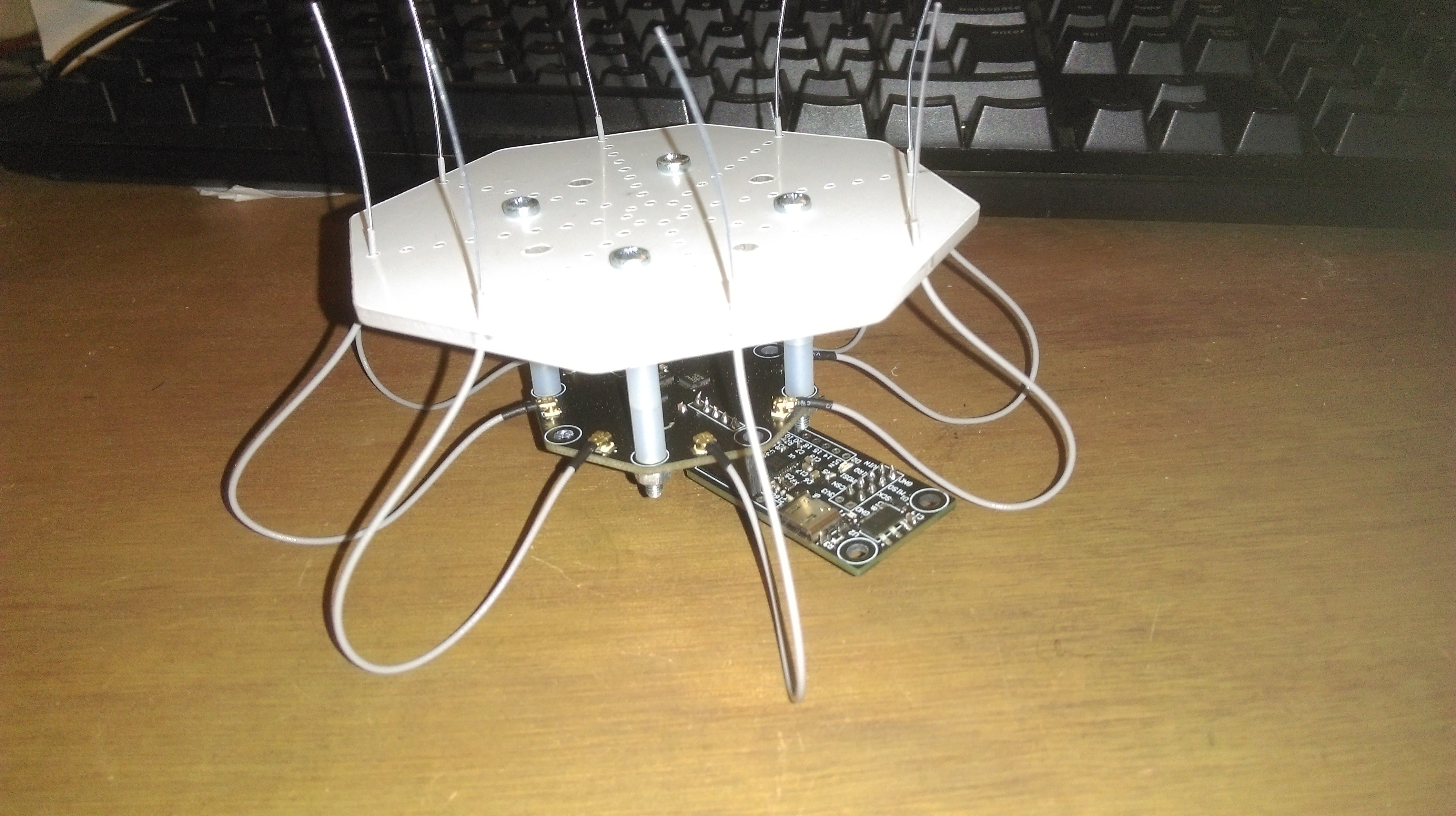 Its a bit difficult to get a good picture of this, but it is roughly speaking the entire ground station. It will be plugged into something else which manages doing something useful with the direction data (such as aiming a camera). The general design is the radio board we have being programming at the bottom, an antenna switch plugged into that (the fancy 4-layer impedance matched one). This has 8 antennas plugged into it, as well as a coax cable going to the radio board (on the side you can't see). I then also have a bit of laser cut acrylic mounted above the antenna switch, which holds the antennas in the shape of the array. With this design, I can change the radius of the circular array (or the entire array shape) by just changing the bit of acrylic used. I possibly need a second one mounted a bit higher up as well to stop the antennas bending (but I will have to experiment with that when I get the direction finding working).
 Modifying the Rx code, I was able to test each antenna in the array, and they all seem to be able to receive data. It is possible that only one works and the switches aren't changing, but with everything staying in the same place, I had some variation in the number of data packets which failed the CRC which seems to be due to alignment. So to me that makes it look like different antennas where being used. If I really have problems, I could disconnect the antennas not being tested as well just to make sure.
With that I'm now at the point where I can program my boards, and the main parts I need to use seem to work. The next step is to get the IQ data and see if I can get my MUSIC code working on this MCU. However, I will leave that for the next log. In the mean time feel free to ask any questions, I've covered everything at a fairly high level because otherwise I wouldn't have time to work on the project, but I can include more detailed explanations in a future log if there is any particular area of interest (I will also do a full write up of how everything works when I have it all working).
Discussions
Become a Hackaday.io Member
Create an account to leave a comment. Already have an account? Log In.