 Charlie Smith
Since the last log I have got the program card to be fully working, so the only incomplete parts to the computer are the input module and the clock. The input module still isn't a priority, and I will talk more about the clock below. I am now able to easily program the computer using my EEPROM programmer and a program card. So I can now start looking at areas to improve, as well as writing more complex programs.
The Stack
This is pretty much my first time using an assembly language properly, so while I could attempt to write some super complex program, it would be better to understand a bit more about how to write programs. Well there is a clear feature I should look into: the stack. The general idea is that we can store values in memory without having to allocate a variable in advanced. By using a stack data structure, we can either push a value onto the stack, or pop a value of the top (you can also peek to look at the top value without removing it). This is often compared to a tall pile of plates. You can either add one to the top or remove one from the top, you can't remove one from the middle (without being very careful). The implementation of this is fairly simple, all that is needed is a large region of memory that isn't used for anything else, and an address pointer (stack pointer) to the top of the stack. To push a value onto the stack we can increment the stack pointer and then place the value in memory at this new address. To pop a value from the stack we can read the value at the current stack pointer, and then decrement the pointer. As this tends to be used a lot, the stack pointer is often implemented at a hardware level, although this isn't required.
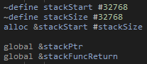
While, we have no dedicated hardware module for a stack pointer, it isn't too difficult to come up with an emulated stack pointer. This can be done by having a global variable in memory for the stack pointer itself. This pointer can go anywhere in memory, but will need to be set to some where the stack should be in memory when the program starts.
We next need to consider how the Push, Pop and Peek functions should be called. Clearly this can't be done in the same way that normal functions are done, as they will use the stack. So for this the general idea is that the function either puts or uses a value in register A, and then jumps the code back to where we where just running. I don't really think there is much use right now of having a dynamic method of getting the current instruction address as a piece of data, so instead we will just set another global variable to where we should jump back too using a label. This example then shows the rough way that a function is used. For each argument (and return location) the value is loaded into register A, the location to return from the stack function is set and then we jump to that stack function. We can then go to that function, which will need to pop the values from the stack, before putting the result back onto the stack. Finally we can pop that value and save it to memory.
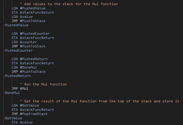
With that in place we can start building more complex programs, making use of functions. For this first example I've defines a multiply function, taking two values from the stack, and putting the result back onto the stack. I think this should actually put the return location onto the stack before the arguments, so as to make calling multiple function calls easier. Anyway, with this function we can now do some more interesting tasks. For example, we can compute factorial numbers up to the maximum we can store (1, 2, 6, 24, 120, 720, 5040, 40320). It will be interesting to implement 32 or 64 bit numbers in the future to allow for larger values, although then we will also need a better method for displaying a number. It did take me a few attempts to get this program (Factorial.asm) working, but was extremely satisfying when it did:
I should note that to get the program working, I was making use of a simulated version of my computer which I should probably make a log on soon.
With this program running, I next considered a few improvements. The first one is that each of the stack functions can actually be performed in single instructions (although they do need most of the 16 micro instructions). This does work in my simulation, but unfortunately it isn't that simple for the physical thing. The issue is a bit complicated, but comes down to needing to decrement the stack pointer by one when popping a value from the stack. As there is no dedicated decrement by one function, we need to subtract one using the ALU. This has the issue of needing to load a value of one into register B, but without being able to pass a value as an OPERAND. A slightly bodged solution is to clear register X, and then increment it by one. This is unfortunately where the problem arises. The only way to clear a single register (as clearly resetting the whole computer isn't going to help) is to have the register load a value, while no value is being set on the bus. However, when trying this, the register will actually get set to have all bits high, rather than low. The data lines are all pulled low by a 1KΩ resistor, so this seems a little odd. However, I believe it is caused by internal pull up resistors in the 74LSxx ICs. I couldn't find anything for the actual register chips being used, but they should be similar to other ICs, for example looking at the 74LS02:
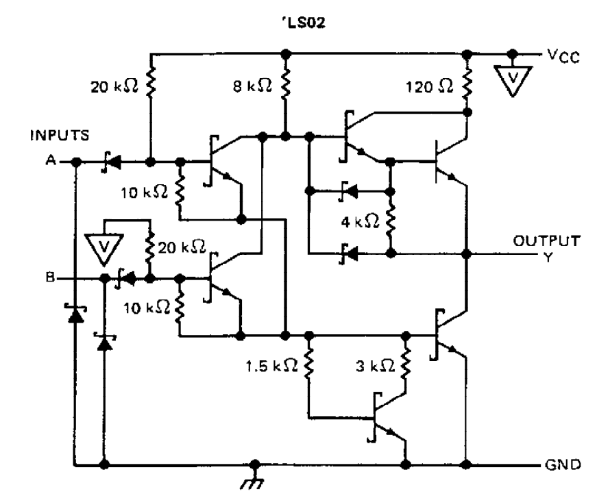
The inputs seem to have 20KΩ pullup resistors. So just considering this single gate (and ignoring the diode as I'm not quite sure what affect it has) this will create a potential divider, and so at 5V will put the undriven voltage at 0.2V. Which is lower than the maximum voltage for a logical low value (of about 0.8V). So while this doesn't seem to be a problem, if we consider that there are quite a few gates connected to these bus lines, its not so simple. There are actually about 10 modules that can read values from the bus, so actually the effective pull up resistance (again ignoring and diodes doing whatever they are doing) is about 2KΩ. So again with a 1KΩ pull down resistor, we will get about 1.7V on the bus when not driven (I seem to measure 1.44V). This is definitely above the maximum for a logic low, and so giving us the high bits. The most obvious solution is to use a smaller pull down resistor, say about 100Ω. This would again give us a voltage of 0.2V. However, this also increases the current from about 0.2mA to 2mA per data line (for a total increase of about 34mA). This probably isn't a huge loss, but the computer already uses a bit more current than I would like, so it isn't ideal.
New Modules
As much as I want the computer to be as simple as possible, there are several new modules that I would like to add. These should hopefully significantly increase the number of aspects of a real computer that I can implement, which is really the goal of this.
Clock
Currently the computer uses the clock designed for the original computer by Ben Eater. Which is on a breadboard, so clearly needs replacing. The clock I had designed doesn't really work, so I need to design something new. While I am at it, I should also redefine what the clock needs to be able to do.
- Manual mode
- Automatic mode
- Automatic mode frequency select
- Can be halted by the control logic
I already have a working manual mode (although I may need to adjust the debouncing) and the halting functionality. So its really just the automatic mode that needs fixing. There are two issues with the existing version. The signal generation needs to be improved, and there is no way to know what frequency is being used. It would also be nice to allow for a higher frequency, just to test how fast the computer can run. There is a fairly simple way that I can change this automatic clock. Rather than using a chip to generate the signal, it doesn't seem too much of a change to instead use an oscillator. This can be quite a high frequency, and then use binary counters to divide the frequency by some power of two. This not only gives a much cleaner clock signal, but also gives a much more accurate one with a known scaling factor, such that the final clock frequency is known. With a 4.1943MHz oscillator and 6 4-bit counters, I can pick a clock frequency all the way down to 0.25Hz. I could also use a lower frequency oscillator and fewer counter chips.
With this new automatic clock, there is one additional function I could now add: a timer. The oscillator will be running all the time, regardless of how the computer is running, what is more it is running at a known frequency. Also, to give the frequency scaling, I need to have counters anyway, so all I need to do is allow for the value stored in the counter chips to be put on the bus. The only issue with this is that a 16 bit value will overflow in 15ms with a 4.1943MHz oscillator. If I had a 32-bit value, it would overflow after 17 minutes. This still isn't a very long time, but much more reasonable and useful. This does however require 8 counter chips. I could reduce the frequency, but I am also quite interested in seeing the the computer can run with a MHz clock, so I would rather not do that. However, I can always start with a 4.19643MHz oscillator, and go to a slower one if I can't run it at that frequency anyway (or need a timer to last longer than 17 minutes). As oscillators have a standardised footprint, I should be able to switch between them fairly easily.
Stack Pointer Register
Rather than rely on a software stack implementation, I could make a dedicated register that can store the stack pointer. This would make stack instructions significantly faster. While I have said that speed isn't really a concern for me, when I have got the compiler functioning, the stack is going to be used a lot more. When this happens, it will likely become a major bottleneck in how fast anything can run, so it would be nice if it only took 3-5 clock cycles per instruction, rather than 15. Luckily, this new register is very simple to design. It is basically a counter register (the program counter and register X), but with a 74LS193 up/down counter.
SPI
This is the main module that was beyond the scope of the original plan. I had thought about some sort of graphical output from the computer, and while this is certainly possible, it requires some memory that needs to be continuously accessed to display the graphics to a screen, while also needing to allow for data to be read from the bus into that memory. I may still try this out in the future, but for now it either requires using chips beyond the limit of what I am willing to use in the computer, or a significant amount of custom logic to achieve this result.
So with a full graphics module out, what can I do instead. Well since starting this project I have done a lot more with microprocessors. These often make use of serial interfaces to communicate to other devices. One such is the interface is SPI. This can be made using shift registers, and so is definitely a feasible addition. What is more is that there are graphical displays that can use SPI, so I am still able to generate a graphical output. Alternatively, there are SPI general purpose input output (GPIO) chips that would allow for lots of other things to be connected up.
C Like Compiler
Since the previous update, I have mostly been working on the C like compiler. This is quite a big undertaking, so it is hardly surprising it is taking so long (I'm also in my masters year at university, so the time on projects is rather limited). There are several parts needed to make a compiler:
- Read source code
- Convert to tokens
- Valid and parse tokens into statements
- Generate assembly code
- Optimise assembly code (optional)
- Save output
However, each of these stages are actually quite complicated, and depending on how they are done, can become quite messy.
Read source code: Generally the simplest part, just requiring the contents of a text file to be read.
Convert to tokens: This is relatively simple, just requiring the input source code to be split up. This can be done by looking for whitespace, or other special characters (e.g. = + - ( ) ...). However, there is some added complication. Firstly, I wanted to allow for standard files (a bit like header files) that a program can include. This means that tokens from another file will need to be inserted in correctly, while also not including a file multiple times. Finally, I wanted to have compile time directives (e.g. #define X or #if X==0 ...). This adds a significant amount of complexity, not least due to needing to evaluate expressions at compile tine. Luckily, I made a system that can be used to do that in the past. This uses the shunting-yard algorithm as a means to convert an expression into reverse polish notation, which can then be evaluated using a stack.
Valid and parse tokens into statements: This is possibly the most difficult part (although I haven't got to code generation yet), requiring some way to take an input stream of tokens, and work out what they mean. An obvious approach to this is to look at each token at a time and use a load of conditional logic to check what type of statement it is in. However, this required a fair amount of what I can only really describe as bodge. The issue is that every possible statement type needs to be hard coded into the system, which is viable for a small number of statements, but makes adding functionally increasingly more complex. An alternative approach is to use an abstract definition of what is a valid statement. This can be done using a tree structure. I also don't want to hard code this, so I needed to make another language to define this in a file. This needs to allow for generating an abstract tree like structure.
- {value} - Defines a statement type with the name given by the value
- [value] - Defines a pointer to another statement type with a name given by the value
- name_value - Defines a name type token with a given value
- numer_value - Defines a number type token with a given value
- string_value - Defines a string type token with a given value
Nodes are split up using a space with any other term being an operator token. When there are multiple child nodes they should be placed on new lines with the same indentation to indicate that the tree branches. For example if we want to add a statement to declare a variable we can use the following:
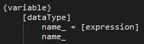
This defines a variable statement that needs the first token to be a valid data type (defined by some other statement). This can then either be followed by a name token with any value, or a name token with any value followed by the = operator, followed by some valid expression statement.
All we need to do now is match this abstract syntax definition with the tokens previously generated and we can not only confirm that the tokens are valid, but we can also build a list of statements along with the tokens associated with them. This still requires a certain amount of hard coding for each statement, but much less than previously, while also separating each statement type.
This is the current part I am working on. I have this working for simple statement, but have had some difficulty with nested expressions. For example I can define something like a = x + 3, but a = ((x + 3) * 4) + y has problems. This comes from how nested expressions get defined:
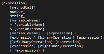
To match the abstract syntax definition with actual tokens is somewhat complex. The method I am using is similar to a pathfinding algorithm. However, the algorithm can easily waste time looking down incorrect infinitely long paths. Consider an expression followed by a binary operator followed by an expression, no tokens are required, so the algorithm can continue looking down an endless chain of these expressions. This could be valid to some level (e.g. a + 1 + 2 + 3 + 4 + 5 + 6 + 7 + 8 + 9...), in general it wastes a lot of time looking down the wrong path. What actually more problematic (and why I haven't got to the next stage of the compiler) is that a branching token needs to be able to check tokens after it, for example ( [expression] ). After the expression finds a valid match, the algorithm needs to also check that there is the operator ). This gets a bit difficult, and currently needs some fixing for complex expressions.
Generate assembly code: Here we need to convert the statements into assembly code. For some things, like variable definitions this should be quite simple. Even statements should be simpler here, using a similar system to how compile time directive expressions where handled. However, things like conditions and structs are likely to get somewhat complex.
Optimise assembly code: This step isn't strictly needed. The code generation stage should produce a valid program. However, to simplify how code is generated, there will be many inefficiencies. For example a value may not need to be stored to memory if it is going to be loaded back in to register A and then never used again, thus some instructions could be removed allowing for the final program to run faster. As the goal of computer isn't to run programs quickly, this stage is likely not going to implemented in full. There are many ways to optimise a program, and while some of them are fairly simple, many are not. It is also very easy to break a program by incorrectly optimising it.
Save output: Finally the assembly code can be saved back to a file, ready to hand to the assembler to make machine code.
Hopefully I can get at least a partially functioning compiler running soon. I specifically want to play around with structs, to see if I can implement larger data types such as a 32 bit or 64 bit integer. The current computer isn't able to display such a thing, but hopefully with the new modules I can make something interesting.
That's it for now. I still need to to a log about the simulation for the computer. However, I would like to make something that you can play around with, so will wait till I find time to work on that.
Discussions
Become a Hackaday.io Member
Create an account to leave a comment. Already have an account? Log In.
Congrats re getting it to mostly work!
I don't know how thoroughly DIY you want to keep this, but reading of your effort to write your own compiler left me wondering if the spirit of your project would allow using something like ANTLR. https://www.antlr.org/about.html (a successor to lex & yacc)
Are you sure? yes | no
Could be useful, I'll have to look into it a bit more. I've managed to get my compiler to generate functioning code, although I've had some issues with code generation for data structures. I should really post another project log about it.
Are you sure? yes | no