 Gee Bartlett
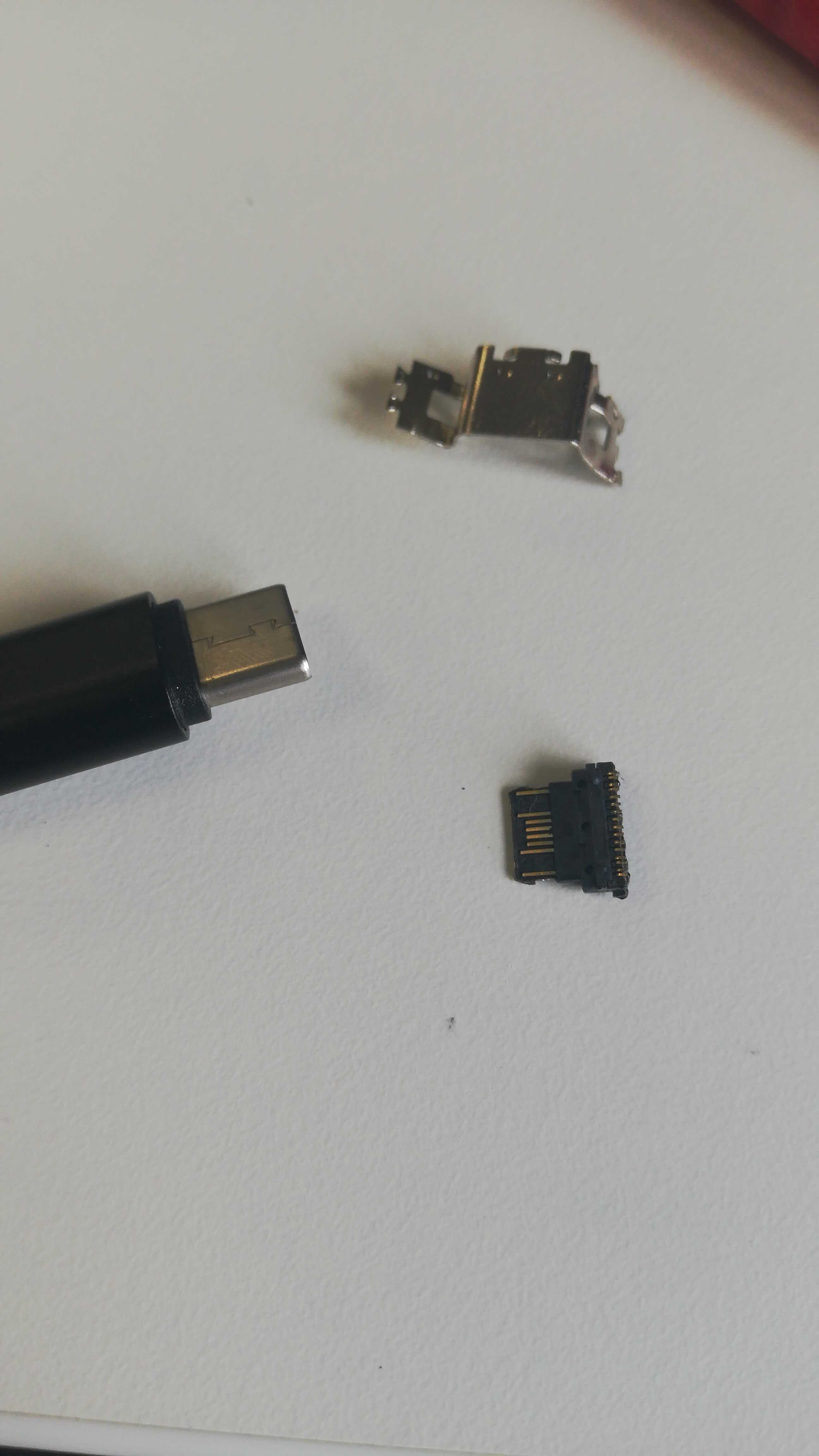
I have been looking at this project for about a month now. So as you can imagine i have done some initial work and investigation, this involved looking into the USB 3.1 specification and tearing apart a a socket or two to see how the connections are made with the USB-C plug.
So it was time to fire up KiCAD and get a design for the socket drawn out. (files available in the Github links provided)
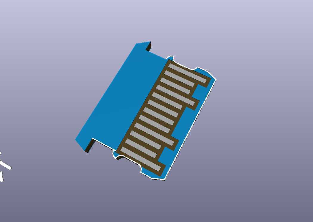
I tried to stick to the specification as much as possible the difficulty is the the sockets 'tongue' should thicken out once it is past the contacts. see below.
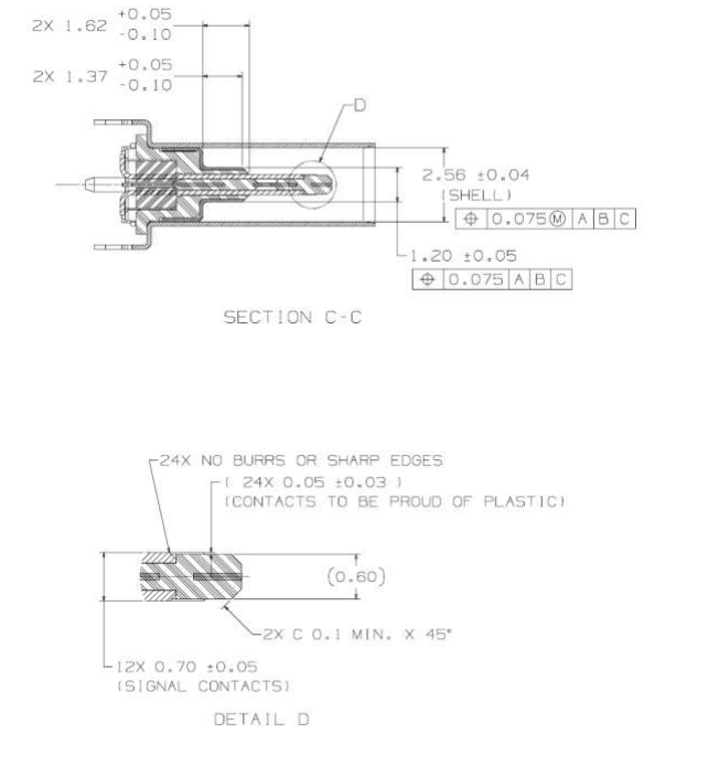
Some who have tried this have reported intermittent contact this could be the reason. In the end I decided to push ahead with a design 0.6mm PCB material.
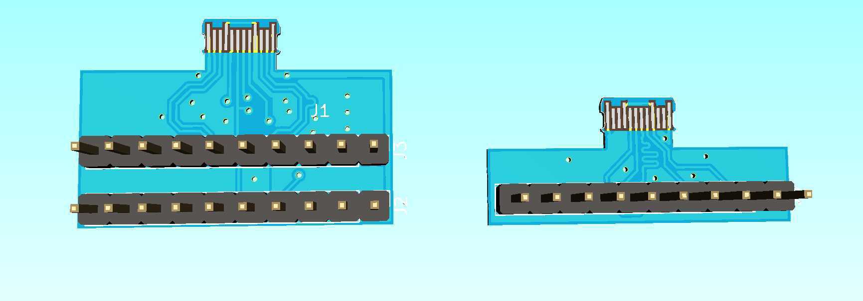
I routed out two designs in the end, The Left-hand design has every contact broken-out from the connector including the differential USB-SS traces all length matched as best as I can. But for the moment I'm going to focus on the right-hand design which breaks out the USB 2.1 traces (length matched to hopefully allow USB-HS communication) VBUS, CC1, CC2, SBUS1, SBUS2 and GND. I want to experiment a little with the Side-Bus as the spec allows low speed transfer might think about trying the 1-wire protocol.
Discussions
Become a Hackaday.io Member
Create an account to leave a comment. Already have an account? Log In.