• Adapting the PAN1780 Headers to Arduino Uno R3 Headers

    parasquid10/18/2020 at 08:35 0 comments

    I'm doing a roadtest of the PAN1780 Evaluation Kit over at element14 and I thought that I'd copypasta over my oneoffs there here as well.

    The PAN1780 doesn't have Arduino Uno R3 compatible headers, which is a shame because a lot of breakout boards are in the Arduino Uno R3 form factor, and it would have been nice to make use of them.

    So I thought maybe I can try and make an adapter using one of the prototyping shields I already have?

    So with a bit of soldering, cross referencing, and wire wrapping I was able to make use of almost all the pins in the PAN1780 and map it to corresponding Arduino pins.

    Some notes:

    • I left out A2 and A3 because pins 02 and 03 (which are ADC pins in the nRF52840) are not exposed via the female headers, and are instead male pin headers located near the NFC pins. I don't know if I would need all six analog-in pins, but if I need to I can just jumper them across. I didn't want to wire wrap directly since I wanted the shield to be easily detachable.
    • I didn't wire 5v yet. I'm not sure if it's even a good idea, because there are many shields that source power from 5v and would therefore use 5v signals for communication. The nRF52840 is not 5v tolerant. Maybe what I can do is short the 5v to 3v3 so there is no danger of higher voltages being sourced, or just provide 5v power separately to devices when I know they don't communicate on that higher voltage. This is similar to the approach taken by the Arduino Nano33 line where they don't provide power to the 5v pins by default and you'd have to solder some jumpers in order to get that working.
    • I tried to match the pins to their functions (e.g. SPI for the default SPI used in the nRF52840DK, ADC pins for the A0..A5 pins, etc) but since not all of the nRF52840 pins of the PAN1780 are exposed, I had to eventually just wire things up so they're neat. I would have to write a lookup table later so if there's a project using the shield, I can just define some constants and I can use those constants instead of the pin numbers (similar to how the Board Support Packages work).

  • Trying Out the Chengdu Ebyte nrf52840 Module

    parasquid09/07/2020 at 08:43 0 comments

    The nrf52 modules I've ordered from aliexpress a couple of months ago have finally arrived, and one of them was an nrf52840 https://psqd.pw/ebyte-nrf52840 module. I've been working mostly with the nrf52832 so I thought I would try and get the nrf52840 to see if the increase in ram and built-in flash are worth the upgrade.

    The module is designated as SMD and comes with castellated edges, with some pads at the bottom. I really like the pin assignments for this module; they cater for both the system integrator as well as the hobbyist. The castellated pins expose the most important pins (power and USB) as well as a generous amount of analog and digital pins. As someone who prefers to prototype with stripboards and donutboards, I don't have to design a PCB just to use the module; I can just wire up the edges with some hookups and I can already have a functional board without much effort.

    In this case, I added double female headers and (on the outside) male headers to help support prototyping.

    I also thought of having something like a shield type of mechanism so I can try things out quickly, but later on I found out that the RF signals are greatly reduced when you cover the antenna (who would have known ...) which isn't that big deal when doing development, but might be an issue when I start trying out BLE related functionality. The module, unfortunately, comes with a chip/ceramic antenna (no IPX connector) so the range isn't the best. I might have to eventually cutout some of the areas with copper pads to try and mitigate the signal loss.

    I added a small 3v Lithium battery and wire-wrapped it to the power connections to try out the module. The nrf52840 (unlike the nrf52832 which has a simpler power connection) has two modes: normal voltage mode and high voltage mode. The datasheet reference circuits for the high voltage mode is a bit too complicated for me at this point, so I opted for the simpler normal voltage circuit where the VDD and the VDDH are connected to the same power source, and VBUS is left floating. I used wire wrap because it's semi-permanent; this can stay as is for months (and even deployed if needed) but it's also easily removed if I need to change anything (which I probably will while experimenting with the power supply configuration). I also added a jumper between the battery ground and the wire wrap as a "kill switch" of sorts; the nrf52 chips are low power, but nothing is lower power than no power :P

    I then progammed the chip using OpenOCD with Espruino (javascript for microcontrollers, just like micropython). While the nrf52840 isn't officially supported (yet) there is a boardfile for the nrf52840DK which is what I used.

    The pins are different of course (the DK exposes all of the chip's pins, and there are built-in LEDs and buttons) but LED1 is mapped to P0.13 and as expected, uploading the default blinky code and adding an LED between P0.13 and GND does blink the LED (I made this LED tester from a while back for the sole purpose of testing blinkies; I'm happy to report that it had proven its worth far more times than I can count).

    Espruino uses the nordic UART BLE service for uploading (and debugging) code, so my small nrf52840 prototype doesn't need to be tethered to my development machine. It's really convenient; I can be testing some circuits and I don't have to worry about ground loops or even being near the actual board (e.g. testing out home automation in a room farther away). Here I placed it on the steel bars on the window via a magnet.


    I initially thought that working with the nrf52840 would be difficult (especially with the normal voltage / high voltage power circuitry) but it turned out surprisingly easy if I default to what I was used to with the nrf52832. But now that the initial tests are over, the next would be discovering how to power the chip via high voltage (the nrf52840 has an internal DCDC and LDO circuits that can accept up to 5v5) as well as trying out the native USB functionality.

  • Multi-input Ammeter

    parasquid08/22/2020 at 08:13 0 comments

    Well this one had a lot of aches and pains, but I managed to finally make it work.

    This was the original idea for the ammeter inspired by Julian Ilett's nice, compact project but with multiple inputs and a flexible output. I basically wanted to not fiddle with wires when setting up the ammeter, and use it just like how one would use a USB tester but not to parasitically draw current from the power source being measured. That way, I can measure power draw over some period of time for projects that would be mostly sleeping, and I can do a good estimate of power draw and battery capacity required.

    I originally thought I'd do the project using an ATTiny85 (a CuteDuino by Cytron, which is now discontinued but it's somewhat a clone of the Digispark) since I had a few of those from a clearance sale. Unfortunately I had a difficult time programming the chip as well as trying to manage memory. So this was a no-go. I'll probably revisit this again in the future, but for the multi-input ammeter it wasn't a good fit.

    I eventually got everything working and connected, using wirewrap. I had to redo the wraps multiple times (thank goodness it was easy) because when I initially soldered everything down, I ran into crosstalk and parasitic capacitance issues with I2C. Even at this point though, there are still some I2C weirdness that sometimes the I2C would just stop ACK or just have strange signals, but at least got the multi-input portion working.

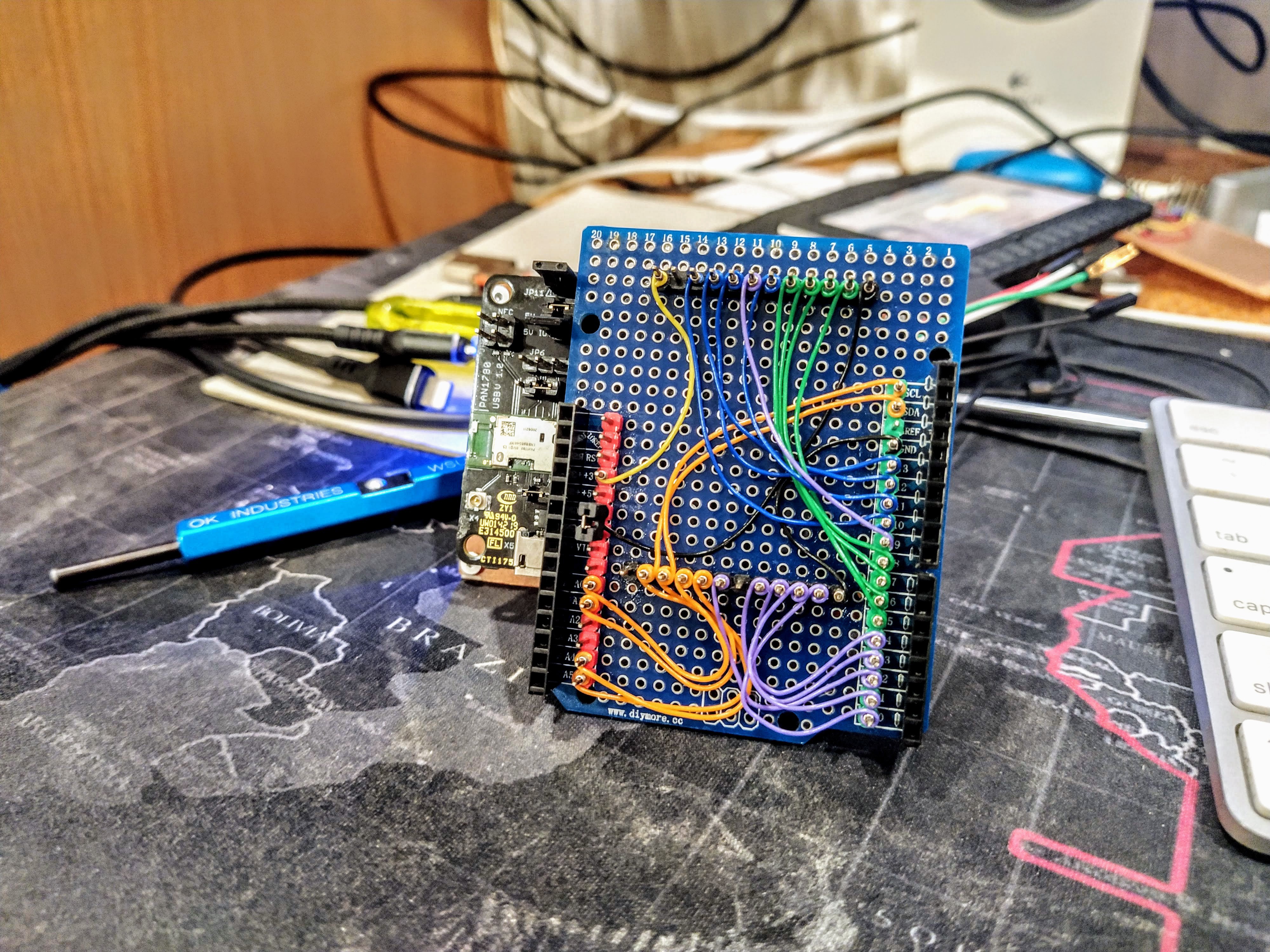
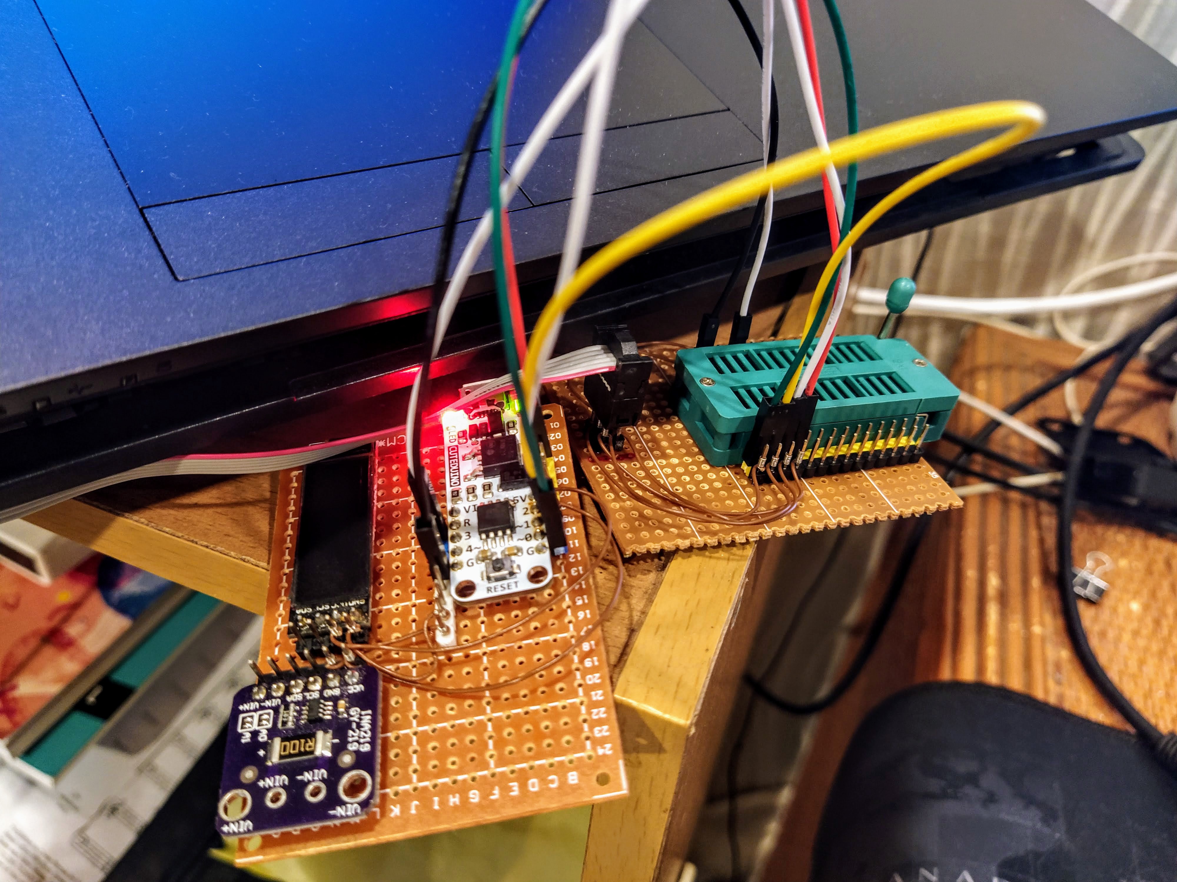
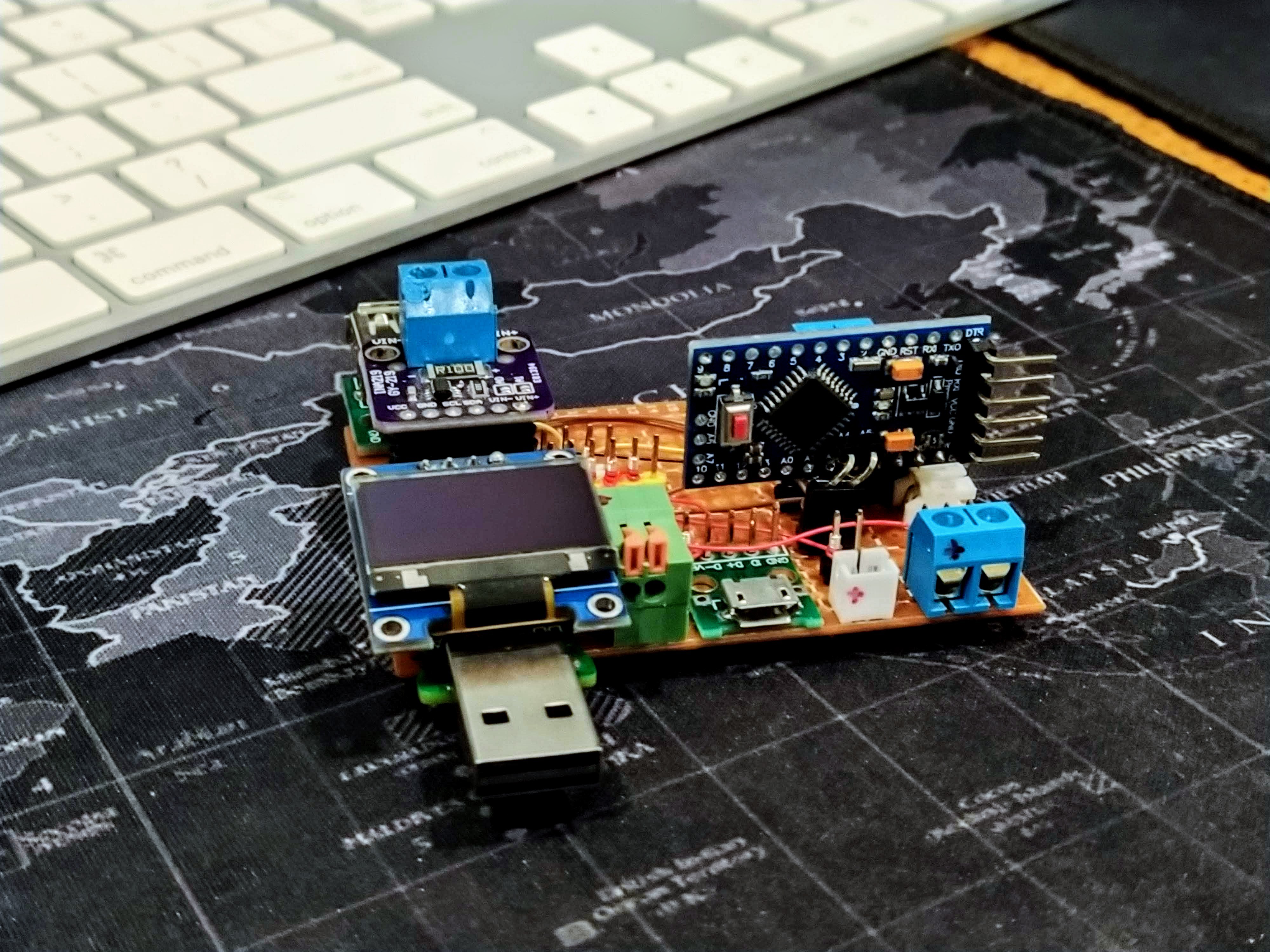
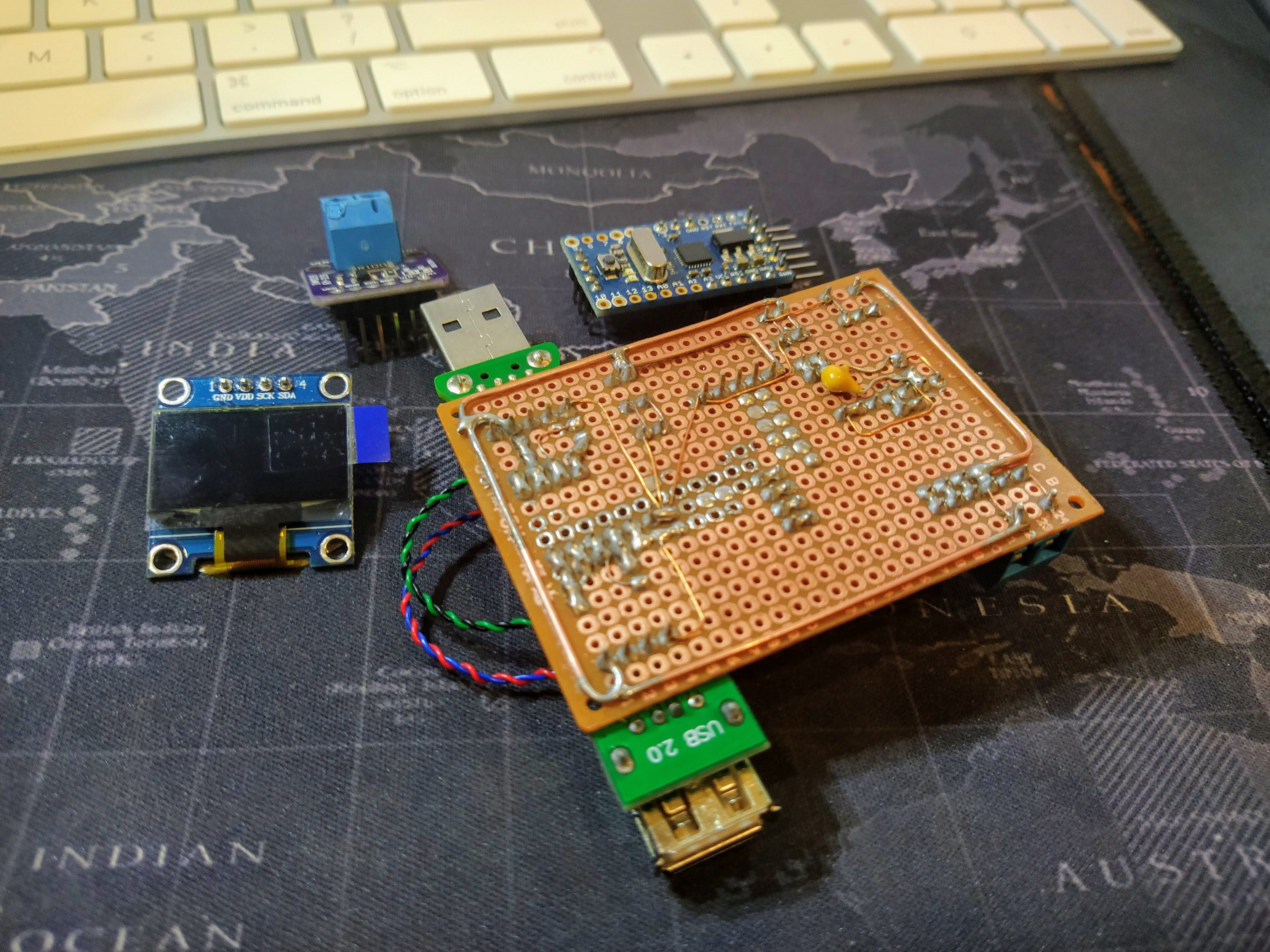
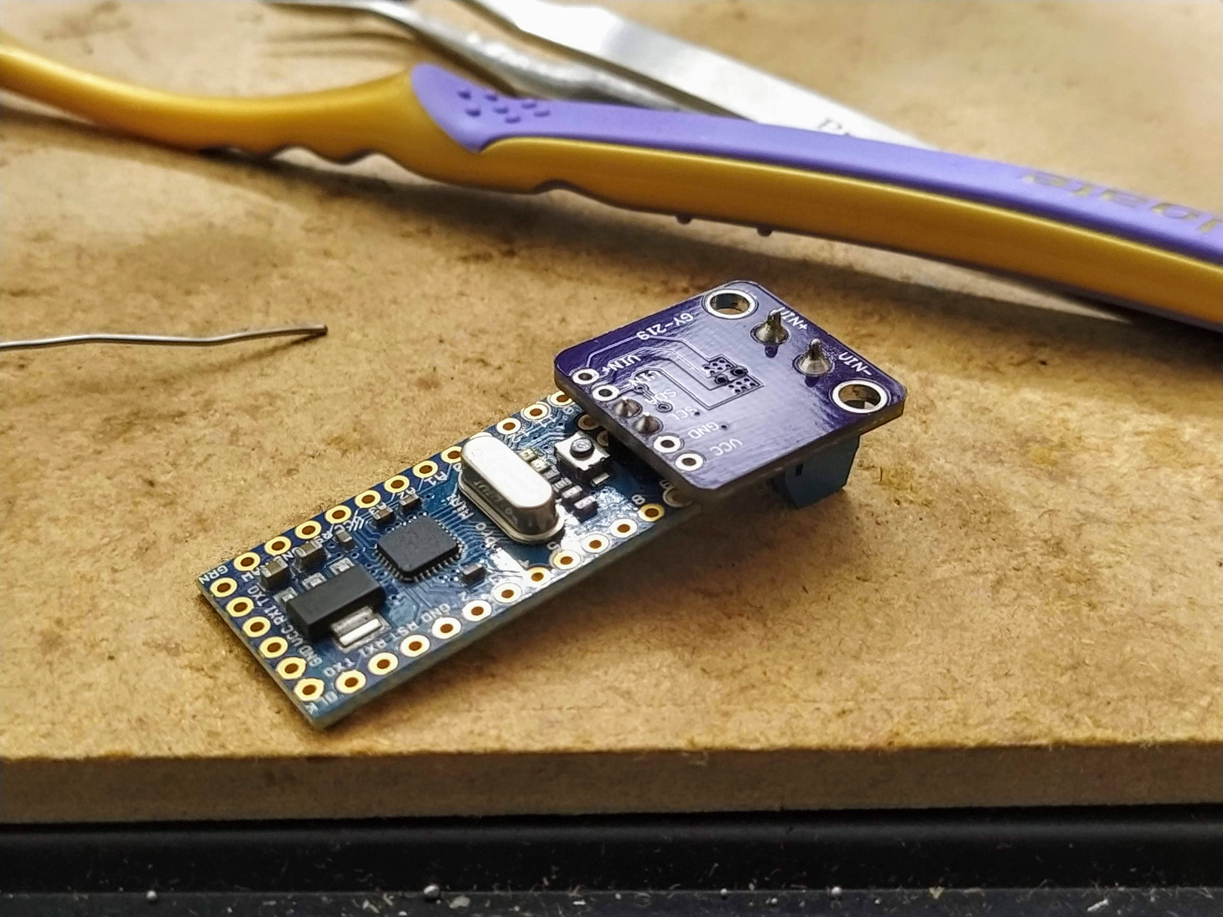
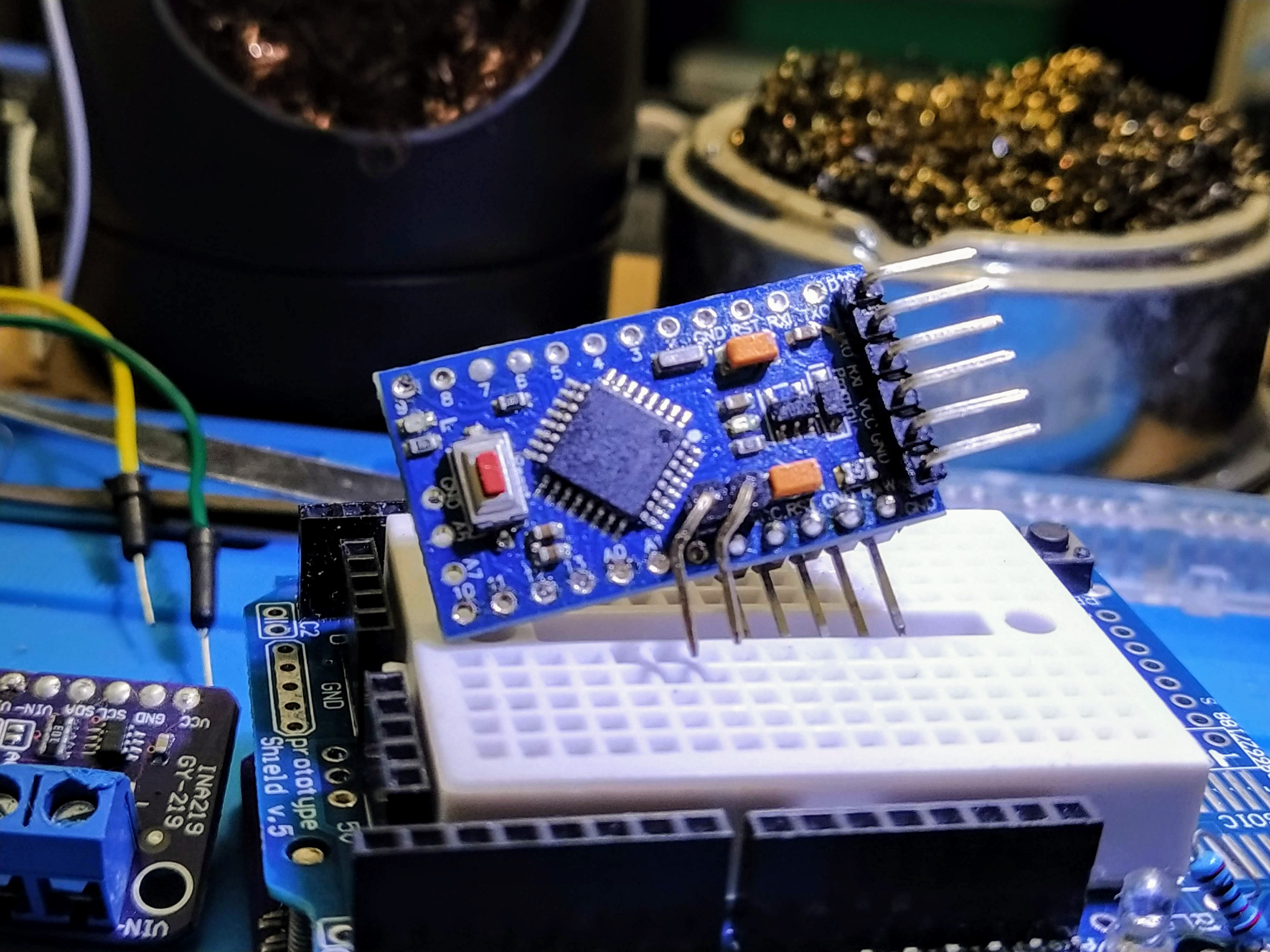
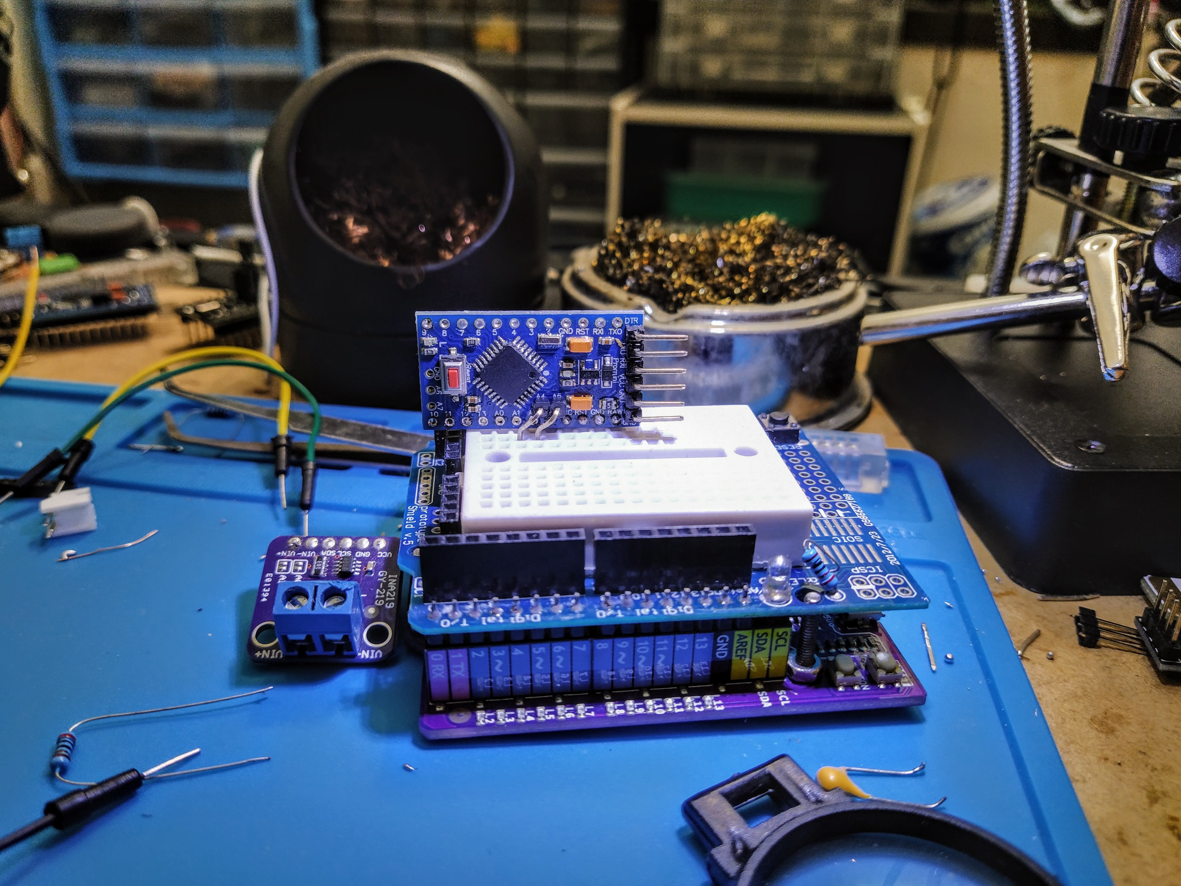
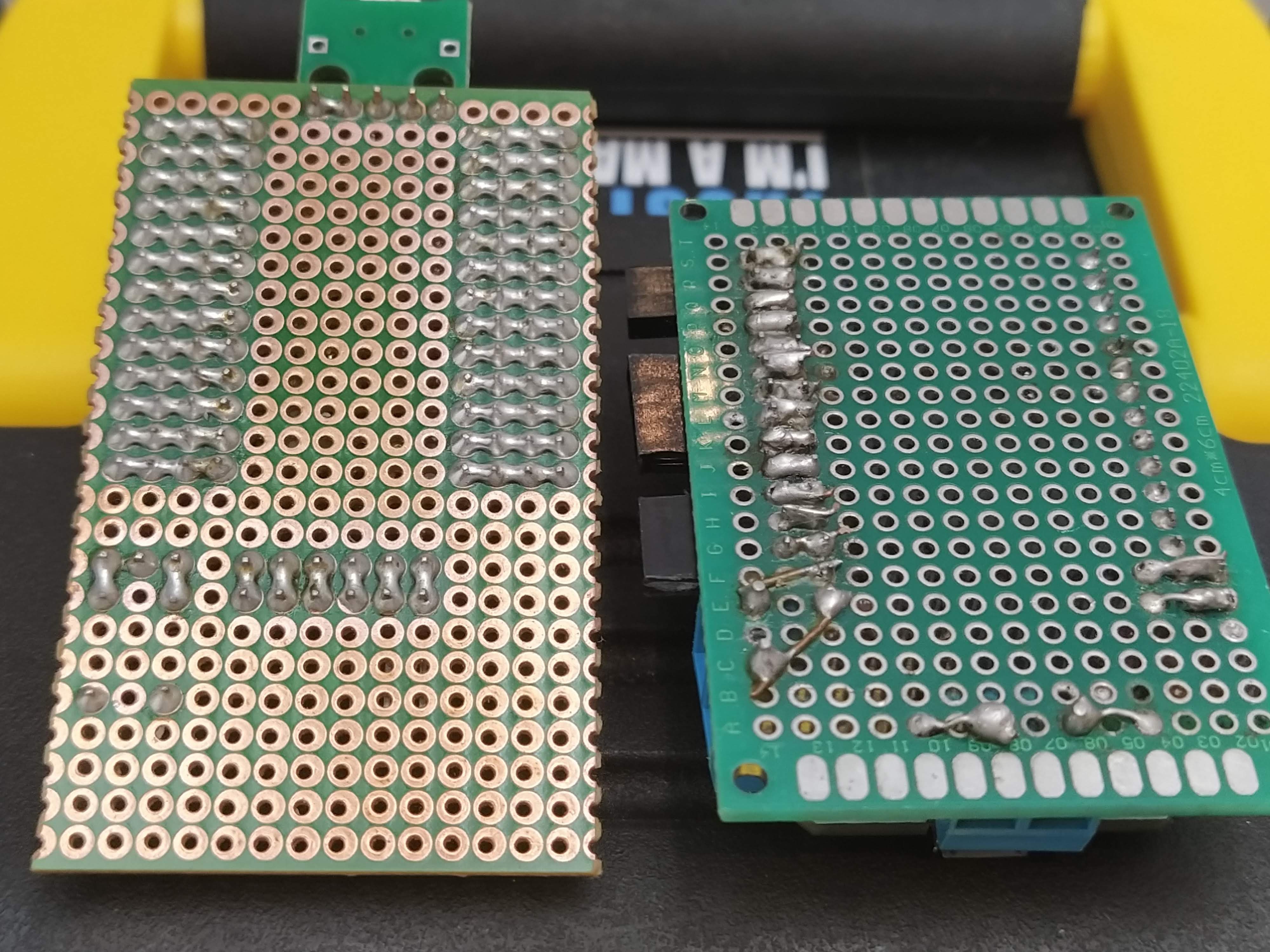
    Then, disaster struck. While I was testing out the project with a powerbank that had a metal case, I accidentally shorted the exposed contacts at the bottom. The oled and the INA219 were fine, but the Arduino Pro Mini didn't survive :( So I had to redo that portion, and considered maybe trying to fix the crosstalk and parastiic capacitance issues with I2C along. So I desoldered all the enameled copper wire and some of the busses I've added for wire wrap (it had served its purpose) and read up on some application notes.

    There was this note in the I2C Bus specification and User Manual by NXP: https://www.nxp.com/docs/en/user-guide/UM10204.pdf#G1661559 which mentions wiring patterns of the bus line. I decided to keep the wirewrap for the I2C connections and use hookup wires for power. This solved the crosstalk issues and the whole ammeter was a lot more stable now.

    I also added a small jumper between the ground of the terminal connector and the Arduino's ground, in case I would want to measure voltage as well.

    And here it is with a USB power bank measuring the current draw of the neopixel light bulb (it goes from 80mA to 150mA depending on the active color). No extra wires in between the high side and the load, as my circuit takes care of that automatically :)

    And how much current does the previous ammeter draw? About 17mA it seems. I've also added another pcb underneath to protect against shorts (secured by a small pink paper clip).

    It's currently running the same four lines from my other ammeter project, but as you can see I have an extra four lines in this display. I'm thinking of maybe latching on to the max current draw as another datapoint to showcase, and possible adding a way to save the latest values onto an external sd card. But those are projects for another day :)

  • Arduino Ammeter Inspired by Julian Ilett

    parasquid08/21/2020 at 13:12 0 comments

    I was inspired by this video that was using an INA219 and an Arduino Pro Mini to make an ammeter, but in a very clean and compact package.

    I didn't have the same pro mini as he did, however. But has that ever stopped a true maker? I still wanted to do it, if only for the challenge :)

    First I soldered male headers to the A4 and A5 pins from the opposite side. This is to give more length to eventually place the 128x32 oled on the other side.

    The INA219 goes to the other side, SDA to A4 and SCL to A5 (so no cross wires here). However that VCC and GND pins are a problem, as I don't have an easy access to the corresponding ones on the pro mini. Looks like I'll have to bodge this one.

    And bodge I did. The oled fits on top as the SDA/SCL locations naturally fall on top of the A4 and A5 pins in the correct orientation (again, no crossed wires) but the GND and VCC pins are quite far off. I decided to just use some hookup wires to get them connected.

    After some programming, I tested it and it works! Not as pretty, but still functional.

    I decided that, unlike Julian's original ammeter that only showed amps, I wanted to show milliamp hours, and volts and milliwatt hours if I connected the ground of the circuit being measured and the amp/volt meter. I prefer flexibility over visibility in this case :)

    #include <Arduino.h>
    
    #include <INA.h>
    #include <U8x8lib.h>
    #include <Wire.h>
    
    INA_Class monitor;
    
    U8X8_SSD1306_128X32_UNIVISION_HW_I2C oled;
    
    unsigned long lastDisplayUpdate = 0;
    
    float bus_V = 0;
    float mAh = 0;
    float current_mA = 0;
    float mWh = 0;
    float power_mW = 0;
    unsigned long lastread = 0; // used to calculate Ah
    unsigned long tick;         // current read time - last read
    boolean toggle = false;
    
    #define error(msg) Serial.println(msg)
    
    void setupDisplay() {
      oled.begin();
      oled.setFlipMode(1);
      oled.setBusClock(100000);
      oled.setFont(u8x8_font_amstrad_cpc_extended_f);
    }
    
    void setupMonitor() {
      monitor.begin(1,100000);
      monitor.setBusConversion(8500);            // Maximum conversion time 8.244ms
      monitor.setShuntConversion(8500);          // Maximum conversion time 8.244ms
      monitor.setAveraging(128);                 // Average each reading n-times
      monitor.setMode(INA_MODE_CONTINUOUS_BOTH); // Bus/shunt measured continuously
    }
    
    void loopDisplay() {
      unsigned long newtime;
    
      oled.setCursor(0,0);
      current_mA = monitor.getBusMicroAmps() / 1000.0;
      oled.print("mA: "); oled.print(current_mA, 2);
      oled.print("   ");
      Serial.println(current_mA);
    
      oled.setCursor(0,1);
      bus_V = monitor.getBusMilliVolts() / 1000.0;
      oled.print("V:  "); oled.print(bus_V, 2);
      oled.print("   ");
      Serial.println(bus_V);
    
      oled.setCursor(0,2);
      oled.print("mAh: "); oled.print(mAh);
      oled.print("  ");
      Serial.println(mAh);
    
      oled.setCursor(0,3);
      oled.print("mWh: "); oled.print(mWh);
      oled.print("  ");
      Serial.println(mWh);
    
      oled.setCursor(11,3);
      oled.print(millis() / 1000);
    
      newtime = millis();
      tick = newtime - lastread;
      mAh += (current_mA * tick)/3600000.0;
      mWh += (power_mW * tick)/3600000.0;
      lastread = newtime;
    }
    
    void setup() {
      delay(1000);
      Serial.begin(115200);
      Serial.println("starting");
      digitalWrite(LED_BUILTIN, HIGH);
      setupDisplay();
      digitalWrite(LED_BUILTIN, LOW);
      Serial.println("oled setup");
      setupMonitor();
      digitalWrite(LED_BUILTIN, HIGH);
      Serial.println("monitor setup");
    }
    
    #define DISPLAY_INTERVAL_MS 100
    
    void loop() {
      unsigned long currentMillis = millis();
    
      if (currentMillis - lastDisplayUpdate >= DISPLAY_INTERVAL_MS) {
        toggle = !toggle;
        digitalWrite(LED_BUILTIN, toggle);
        loopDisplay();
        lastDisplayUpdate = currentMillis;
      }
    }
    

  • BLE Espruino Controlled Neopixel Mini Lightbulb

    parasquid08/20/2020 at 09:13 0 comments

    I ordered some bare NRF52832 ebyte modules ( affiliate link: psqd.pw/ebyte-bare ) from a local reseller while waiting for the modules to arrive from China, since I wanted to work on a project but didn't want to wait too long. While they did arrive earlier than the modules from aliexpress, there was some unexpected issues:

    It seemed that the modules had either been through some vacuum process, or something really heavy was put on top of them, squishing the rf shield.

    In fact, the rf shielding easily came off while I was inspecting the damage.

    It was just the rf shielding, so I was hoping that the chip itself wasn't damaged. So I quickly made up a small jig to program the chips through SWD:

    I used pogo pins so the jig will have good contacts with the module, instead of soldering the wires to the chip (I wanted the jig to be reusable).

    As a quick test, I programmed the MDBT42Q Espruino firmware onto the module via SWD and some wire grabbers (I also soldered some extra male header pins without their plastic base so its easier to grab the wire). It doesn't look pretty, but I didn't need it to be; I just needed it to work :P

    And work it did, I was able to flash Espruino on both modules so at least they are still viable somewhat. However, I don't trust the module's stability anymore and I probably won't be using them for something important, so I thought maybe I'll use them for some projects I've had in the backburner instead?

    I did have one, which is a mini-light bulb whose led I wanted to replace with some neopixels, and controlled via BLE. I had a few presentations in mind and one of them would be this one (alongside the neopixel matrix I talked about in one of these logs).

    The module barely fits in the bulb housing, but that's actually an advantage as I can just tape the neopixel above the module. I also used an AMS1117 3v3 voltage regulator to drop the voltage from USB 5v to 3v3 for the microcontroller, while passing the full USB 5v to the neopixel. I probably should have used a capacitor for smoothing but I was just interested in whether the thing works.

    And here it is lighting up and running a rainbow pattern. The original LED from the bulb is near the bottom of the power bank. Unfortunately, it seems the glue that I used was exothermic and nearly melted the plastic base near the USB male connector :( If I ever have to redo this project, I'll have to be careful about that.

    No code for now since this was supposed to just showcase how Espruino can run and be useful in even a small device like a light bulb. Theoretically I can put the neopixels and the microcontroller onto a full 220v LED bulb, but I'm not an electrician and working with mains is always dangerous :P So I work with 5v and just leave the possibilities to the imagination.

  • Connecting to the Arduino Pro Mini A4 and A5 I2C Pins

    parasquid08/18/2020 at 18:40 0 comments

    I needed to use I2C on a project with an Arduino Pro Mini, but on this model the A4 and A5 pins are 0.5in shifted and so wouldn't easily fit on a bread board without some gymnastics. I found a good way to bring them out, but it's only useful if you don't need to bring out all of the pins of the mcu.

    I used right angle pin connectors on the raw/gnd/rst/vcc side and long pin 19mm connectors facing upwards on pins A4 and A5. Then I bent them down and angled a bit to compensate for the shift.

    Here it is comfortably sitting on a breadboard. You do lose access to the top (mostly digital) pins, but depending on the project it may be a sacrifice that's worth it.

  • DIY LiPo Battery Shield

    parasquid08/18/2020 at 18:27 0 comments

    When I make projects based on the Arduino Pro Mini, it was often more convenient to prototype them with a full size Arduino. However, unlike the 3v3 pro mini where I can just plug in a lipo battery through the raw and gnd pins, I'll need to tether myself to a cable and power supply for the Arduino. I can't really use most of the power banks I have because sometimes the Arduino would sip too little current that the power bank turns itself off.

    I've looked online for LiPo battery shields but found them all to be on the more expensive side, so I decided to DIY my own.

    It starts with the TP4056 module with lipo protection. I soldered a two-pin JST header on the battery in/out, spreading the legs so they reach the terminals. It was surprisingly sturdy. I didn't want to solder in the batter wires because the lipo I was using already came with nice silicone wires with a JST connector, and I didn't want to cut that off. Plus I get the option to use a different lipo battery later on if needed.

    Since the Arduino I'm using has a USB micro input, that's what I'm using for the jack. I had to boost the power to 5v using a boost converter since the lipo can only output 4.2v max. After checking polarities, some heatshrink tubing and some testing, it's time to assemble the shield.

    I already had a protoyping shield with a lipo battery attached and a mini breadboard with double sided tape, so I decided to reuse that. After plugging everything in, I confirmed that it's working and running the sketch that I was using for prototyping my other project. This way, I don't need to be tethered to any cables if I'm not doing any programming.

    Should the battery go flat, the TP4056 is there to both charge the battery and provide power.

    I think this is really convenient. I've been thinking about making one, and I'm glad I was finally annoyed enough to actually make one.

  • ESP32 Cam Dev Board

    parasquid08/15/2020 at 10:50 0 comments

    The You tube algorithm decided to show me some ESP32 Cam videos and I remembered I had a couple in storage. So I thought, why not try it out again and refresh my experience with it?

    So I brought out my perfbaord and wire wrapping tools and decided to create a more or less generic board for the module.

    That's really all there is to it. Double rows of female headers (to accommodate male dupont connectors), male headers on the inside for the semi-permanent wire wrapped connections, and male headers on the outside for female dupont connections.

    There's also the serial 90-degree bent headers for connecting the USB-serial programmer (its pin order is that of the Arduino pro mini, but since this is a wire-wrapped jig, it's not that difficult to change the assignments if I ever want to assign a permanent USB-serial programmer for this dev board).

    I also added a button that would pull GPIO0 to ground since that's required to bring the ESP32 Cam to bootloader mode (hold it down on startup to enter that mode).

    Speaking of wire wrap tools, I have a counterfeit clone bought from a well-known chinese website, as well as the original one bought from digikey:

    They function mostly the same, but there are some subtle differences:

    * the clone takes in a couple mm of the kynar coated wires when inserted while the original just stops the wire insulation right at the lip. The pvc insulation is too thick for either tool to ingest.

    * the original has a much sharper insulation stripper (although this may be due to the fact that I use the clone more)

    * the original has more heft and weight to it, and feels more "premium" (like steel vs aluminum)

    * pvc coated wires wrapped with the original tend to overlap, while I generally have no issues with wrapping on the clone; I don't have any issues when wrapping with kynar coated wires on either of them

    Also, while trying to find the ESP32 Cam I saw an old dev board I made for the ESP32 NodeMCU:

    The left one is the dev board I just made, and the right one is the dev board I made a some time ago. Hard to imagine I soldered like this back in the day!

  • Bluetooth Low Energy controlled Neopixel Matrix

    parasquid08/09/2020 at 07:07 0 comments

    I accidentally lifted the pads off of my Ebyte nrf52832 bare module (affiliate link: https://psqd.pw/ebyte-bare ) and that means I won't be able to use it as a development and test board anymore.

    That also does mean I can use it on a more permanent fixture, so that's what I did.

    I've been looking to have my neopixel matrix more autonomous by connecting it with a wireless microcontroller and having that as a single unit. This ebyte module is perfect to integrate with the matrix, giving me the ability to control it remotely via Bluetooth Low Energy.

    I've already installed Espruino on the module, so all I needed was some sticky tack and wires (and a 3v3 regulator I salvaged from another project that didn't quite go as planned).

    I added the button because Espruino supports DFU updates and you do that by holding BTN1 (which in this firmware was P14) during bootup.

    Here's the javascript program for the BLE control:

    const neopixel = require("neopixel");
    
    const rows = 8;
    const cols = 8;
    const bpp = 24;
    const ledCount = 64;
    const pin = 25;
    const leds = Graphics.createArrayBuffer(
      rows,
      cols,
      bpp,
      {
        zigzag:true,
        color_order: 'gbr'
      }
    );
    leds.flip = () => { neopixel.write(pin, leds.buffer); };
    
    
    const scale = (num) => num / 0xFF;
    
    NRF.setTxPower(4);
    NRF.setServices({
      "0x181C": {
        "0x2A3D": {
          value: [0,0,0,0,0],
          writable : true,
          description: "sets the value of a pixel: [r, g, b, x, y]",
          onWrite : function(e) {
            const data = new Uint8Array(e.data);
            leds.setColor(scale(data[0]), scale(data[1]), scale(data[2]));
            leds.setPixel(data[3], data[4]);
            leds.flip();
          }
        }
      }
    }, { advertise: ['181C'] });
    
    
    NRF.on('disconnect', function() {
      leds.clear(true);
      leds.flip();
    });
    
    E.on('init', function() {
      NRF.setConnectionInterval(7.5);
      console.log("Hello World!");
      leds.clear(true);
      leds.flip();
    });

     If you write a byte array of [r, g, b, x, y] to the 0x2A3D characteristic, that particular pixel in the matrix will light up. Disconnecting will clear the whole matrix.

    The whole thing was done at the back, so all that really shows up in front is the power cable.

  • ATTiny85 Programmer

    parasquid08/08/2020 at 15:25 0 comments

    It's been a while, and I was thinking of revisiting the ATTiny85 chips which I bought a number of back when it was the "in" thing as far as Arduino replacements were concerned.

    I had a few things I knew I should be using:

    • a ZIF socket (I had a few lying around) so it's easy to program a chip and then remove it. I didn't have much luck with IC sockets and I didn't have the one specifically for the 8-pin chips.
    • wire wrap. I initially thought that since I was using a longer ZIF socket than needed, I can also program other chips just by redoing the wire wrap (which would be much easier than desoldering wires) making the programmer quite versatile. The wire wrap actually made it easier for me to wire the ICSP headers because I made a number of mistakes getting the correct pins to be connected to the programmer, it didn't take a long time to do over the wires until I got it working.
    • USBasp. The ATTiny85 had such small ram and flash that having a bootloader isn't very wise, so having a dedicated programmer would save me the space that a bootloader would have used.
    • double pin headers. After programming I might want to hook up the chip to some external devices, so I would like this programmer to double up as a development board too. So the outside row would be where I do the wirewrap, and the inside row would be where I can connect dupont cables to.

    After a couple of hours of soldering and wire wrapping, it works!

    One tip I've learned through experience is to mark the red line in the ICSP header, just so there is no ambiguity over which side the cable should be.

    How do you know when it's working? When it can run blinky of course :)