 parasquid
Well this one had a lot of aches and pains, but I managed to finally make it work.
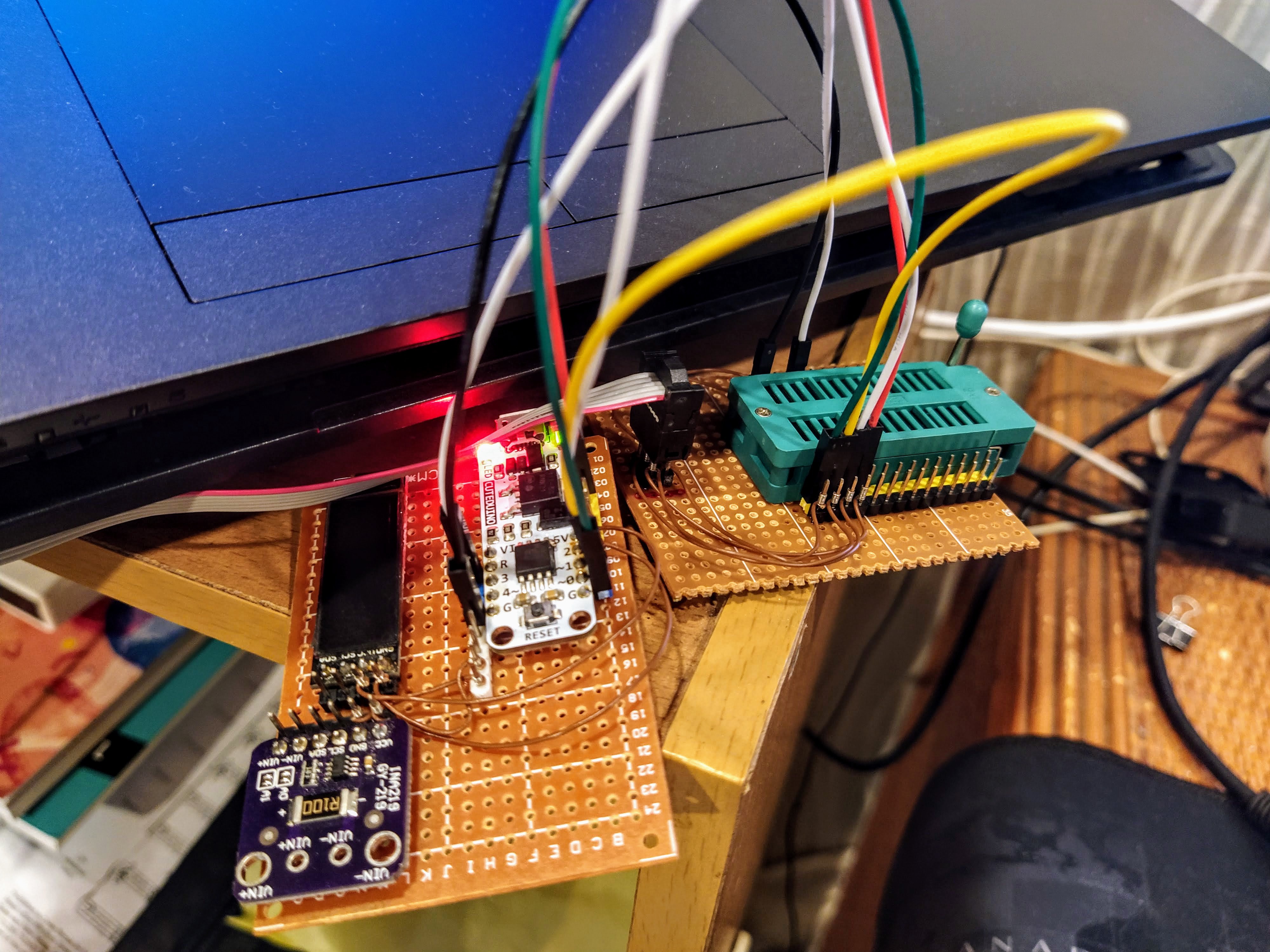
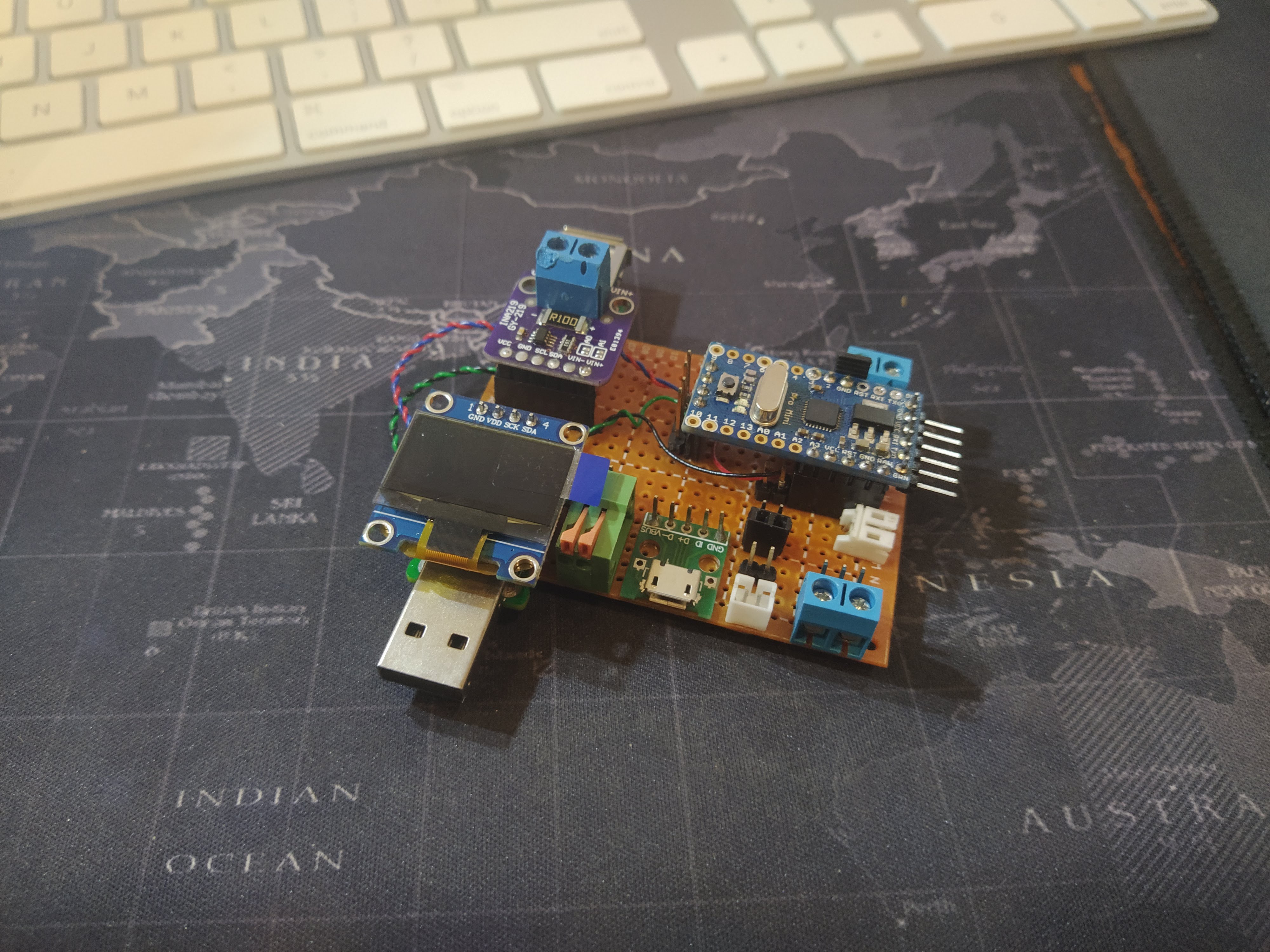
This was the original idea for the ammeter inspired by Julian Ilett's nice, compact project but with multiple inputs and a flexible output. I basically wanted to not fiddle with wires when setting up the ammeter, and use it just like how one would use a USB tester but not to parasitically draw current from the power source being measured. That way, I can measure power draw over some period of time for projects that would be mostly sleeping, and I can do a good estimate of power draw and battery capacity required.
I originally thought I'd do the project using an ATTiny85 (a CuteDuino by Cytron, which is now discontinued but it's somewhat a clone of the Digispark) since I had a few of those from a clearance sale. Unfortunately I had a difficult time programming the chip as well as trying to manage memory. So this was a no-go. I'll probably revisit this again in the future, but for the multi-input ammeter it wasn't a good fit.
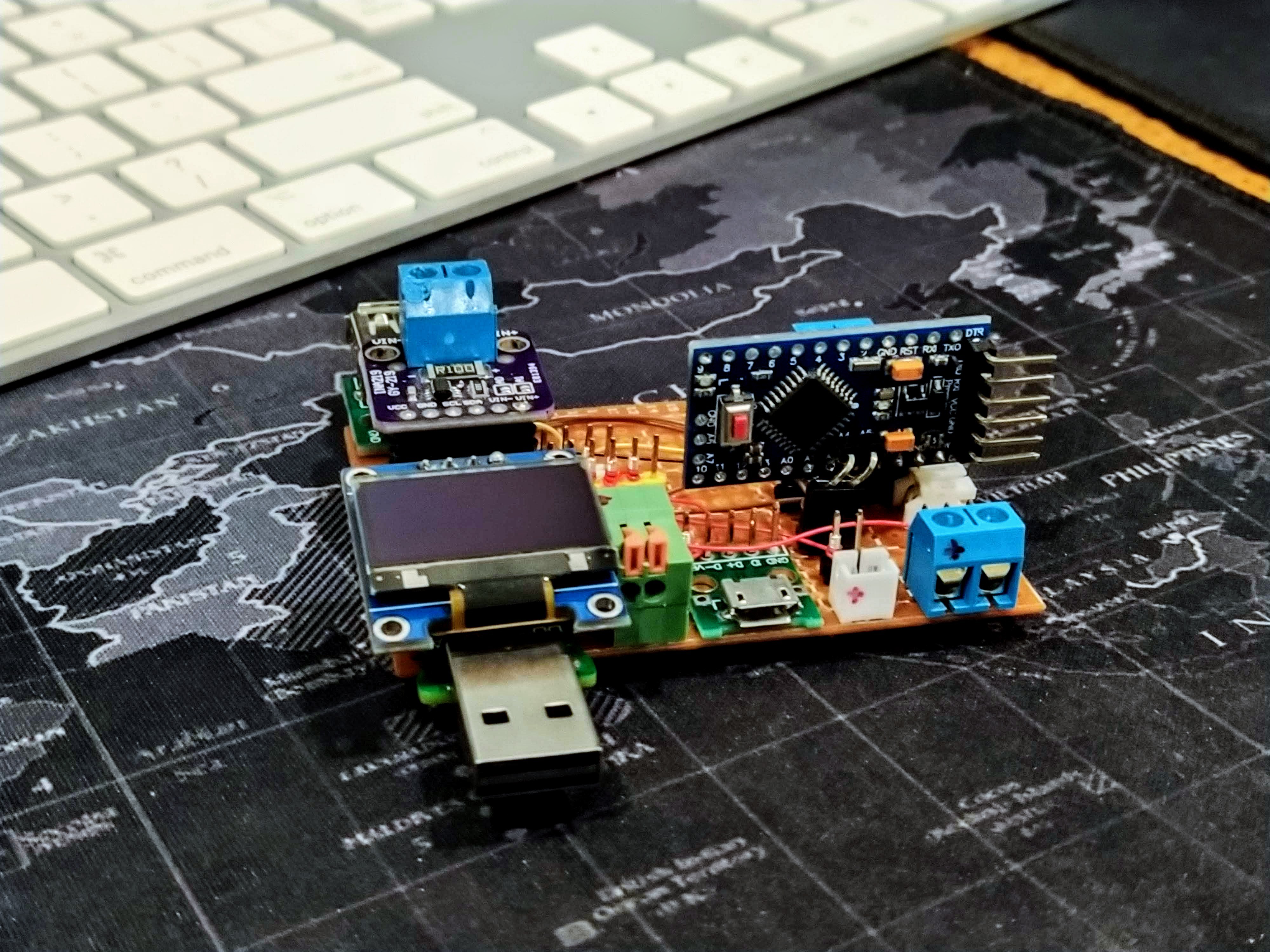
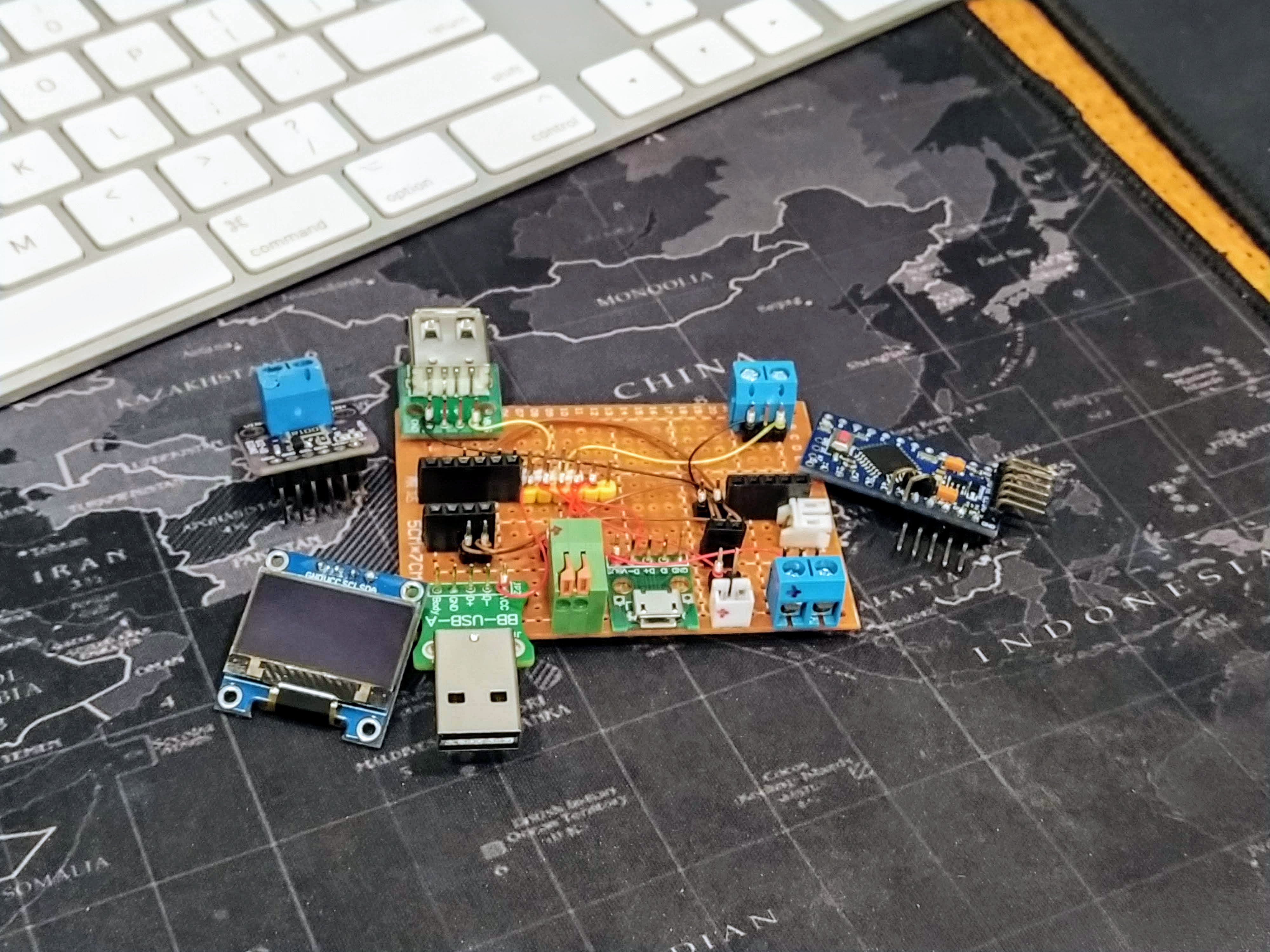
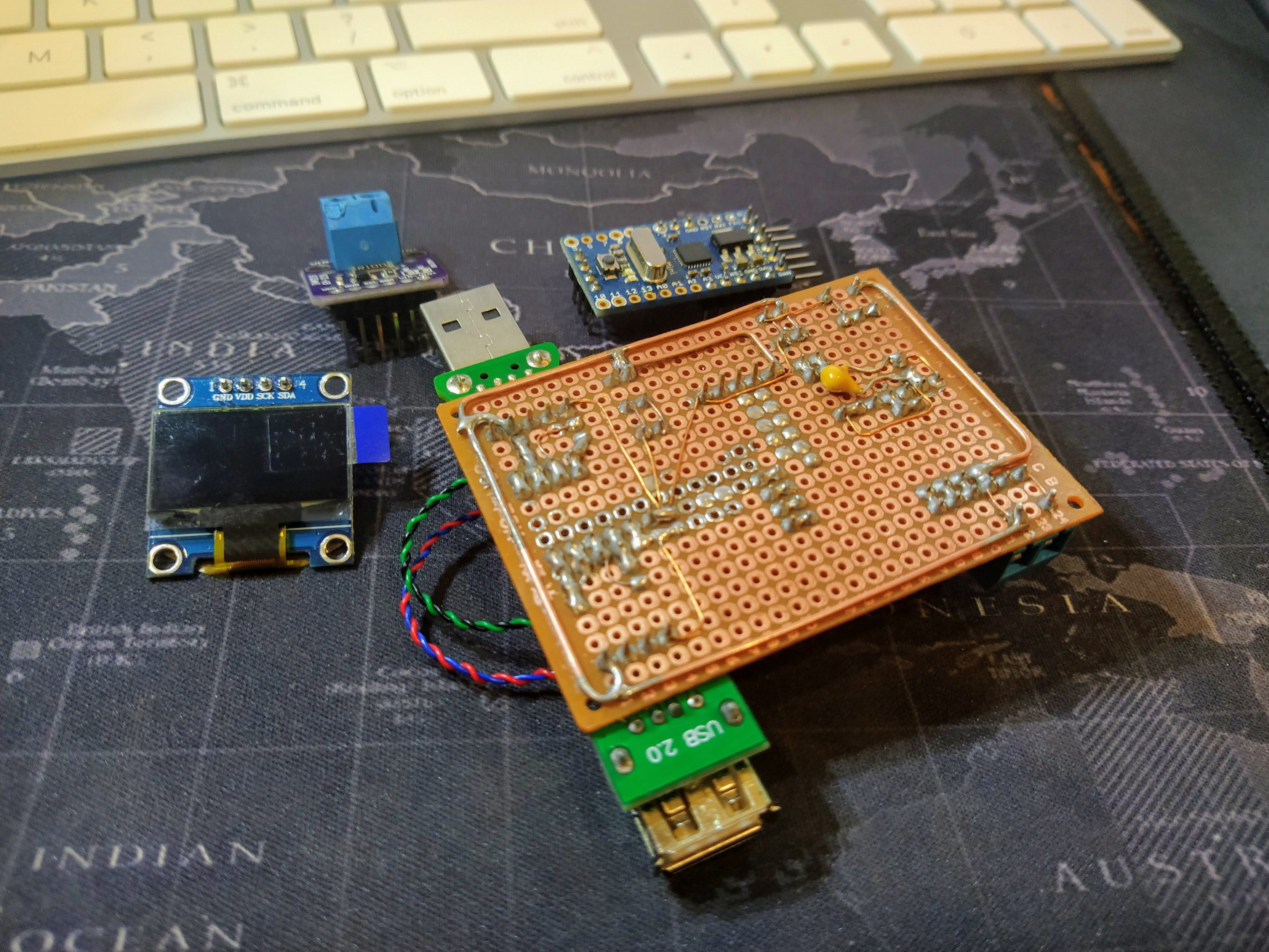
 Then, disaster struck. While I was testing out the project with a powerbank that had a metal case, I accidentally shorted the exposed contacts at the bottom. The oled and the INA219 were fine, but the Arduino Pro Mini didn't survive :( So I had to redo that portion, and considered maybe trying to fix the crosstalk and parastiic capacitance issues with I2C along. So I desoldered all the enameled copper wire and some of the busses I've added for wire wrap (it had served its purpose) and read up on some application notes.
There was this note in the I2C Bus specification and User Manual by NXP: https://www.nxp.com/docs/en/user-guide/UM10204.pdf#G1661559 which mentions wiring patterns of the bus line. I decided to keep the wirewrap for the I2C connections and use hookup wires for power. This solved the crosstalk issues and the whole ammeter was a lot more stable now.
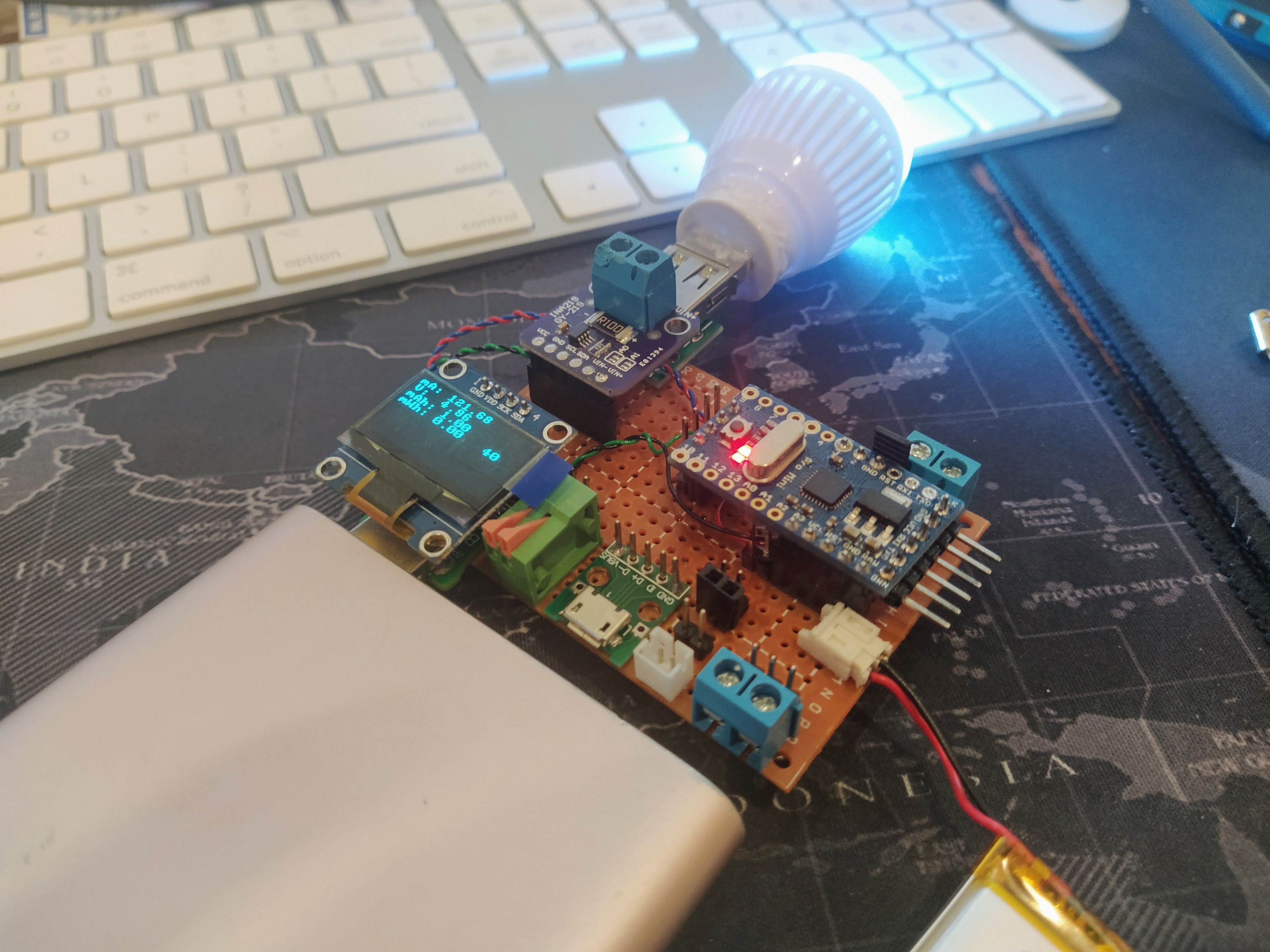
I also added a small jumper between the ground of the terminal connector and the Arduino's ground, in case I would want to measure voltage as well.
And here it is with a USB power bank measuring the current draw of the neopixel light bulb (it goes from 80mA to 150mA depending on the active color). No extra wires in between the high side and the load, as my circuit takes care of that automatically :)
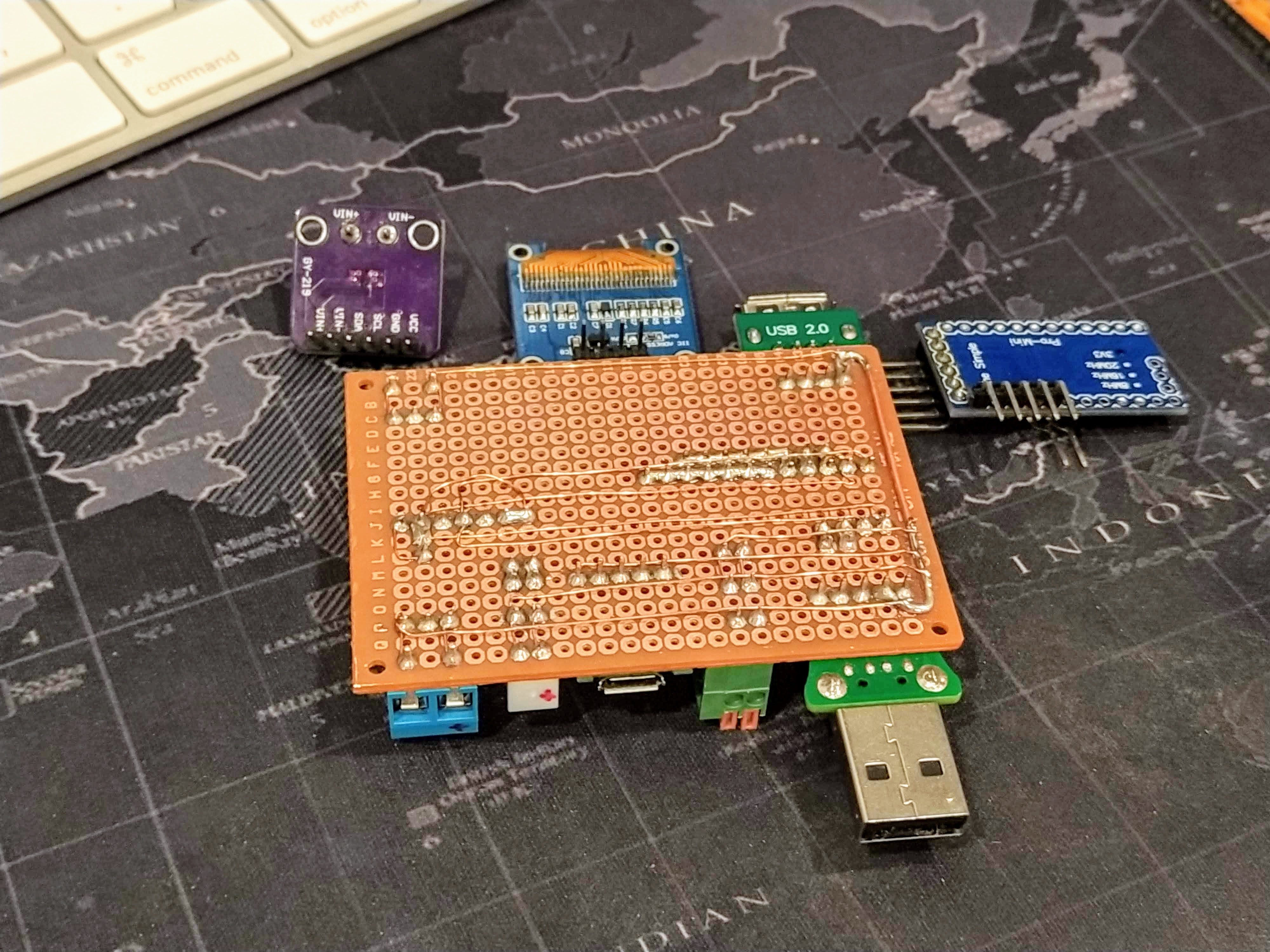
And how much current does the previous ammeter draw? About 17mA it seems. I've also added another pcb underneath to protect against shorts (secured by a small pink paper clip).
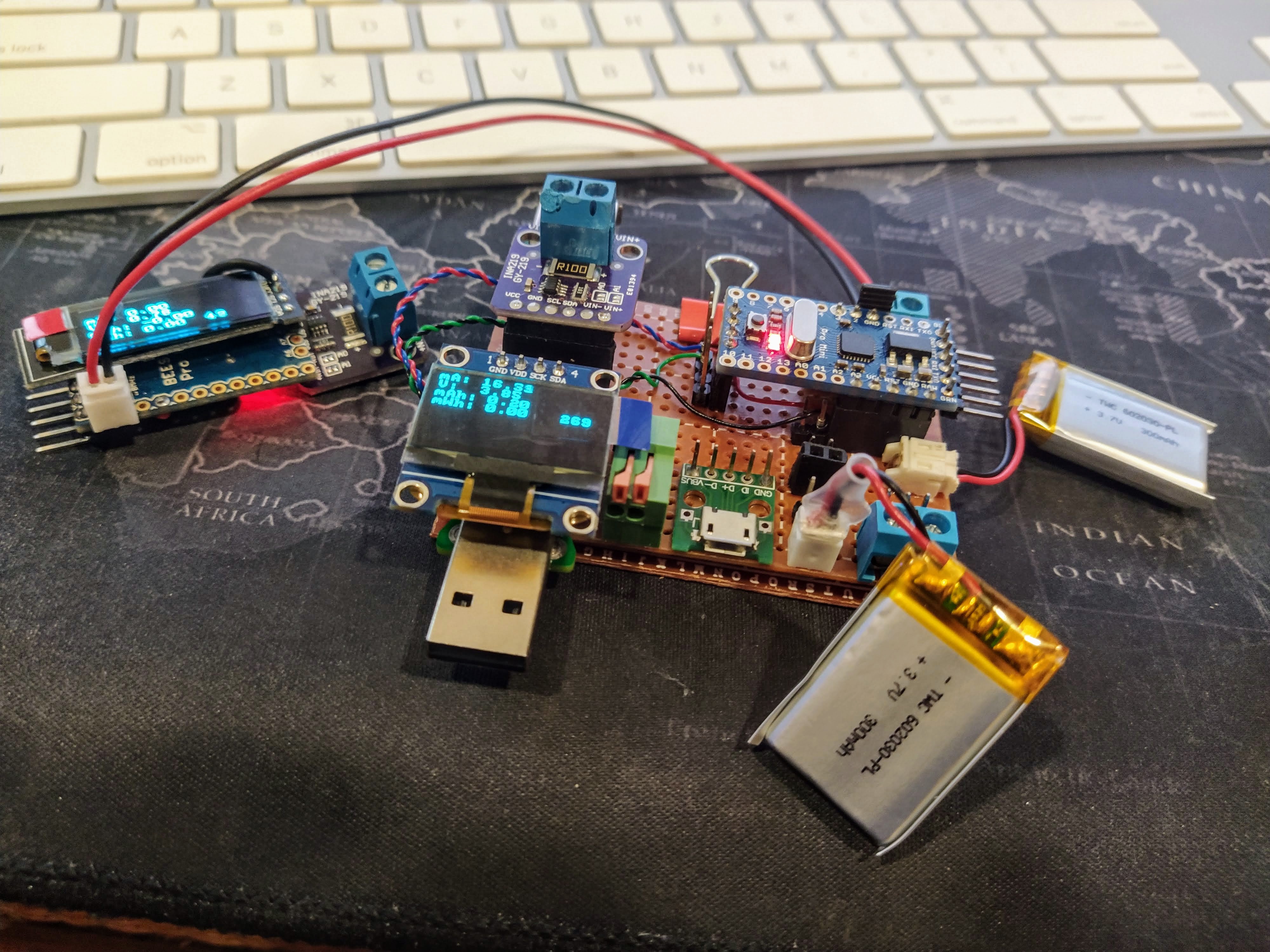
It's currently running the same four lines from my other ammeter project, but as you can see I have an extra four lines in this display. I'm thinking of maybe latching on to the max current draw as another datapoint to showcase, and possible adding a way to save the latest values onto an external sd card. But those are projects for another day :)
Discussions
Become a Hackaday.io Member
Create an account to leave a comment. Already have an account? Log In.