 Christoph Tack
Theory
Channel capacity
Shannon-Hartley law: where C is channel capacity [bps], B is bandwidth [Hz] and S/N is signal/noise ratio.
Example: dPMR (C = 4800bps, B=6250Hz). So S/N must be at least 0.70.
Number of bits/symbol needed
Nyquist's Theorem :
Example: dPMR (C = 4800bps, B=6250Hz). So N is 1.3bits/symbol.
Noise floor
–174 dBm is the thermal noise floor at room temperature in a 1-Hz bandwidth.
e.g. for 10kHz bandwidth, the noise floor is -134dBm.
(see Long-range RF communication: Why narrowband is the de facto standard, Texas Instruments)
Legal limitations
We can only make use of unlicensed bands. Some bands only allow pre-certified equipment and fixed antennas. Here are some options for unlicensed spectrum. I left out the <100mW options and constrained myself to the sub-1GHz options. If you're looking for a DIY-solution for 2.4GHz, have a look at the nRF24Audio library.
27MHz
- Citizen band : 12W, SSB, 10kHz channels, 26.690MHz to 27.410MHz, some channels excluded
- Packet radio Germany : 27.235 MHz and 27.245 MHz
- Packet radio Netherlands: 27.235 MHz and 27.395(wikipedia)/27.405 MHz
- Packet radio Belgium : forbidden
- SRD : 100mW, 5 10kHz wide channels around 27MHz, <0.1% duty cycle
169MHz
- SRD : 0.5W, 169.4MHz to 169.475MHz, 50kHz channels, <1% duty cycle : BIPT B01-10
446MHz
- PMR446 : 0.5W, ,6.25kHz or 12.5kHz, 446MHz to 446.2MHz
- dPMR446 aka dPMR tier 1, ETSI TS 102 490 & ETSI TS 102 587.
823-832MHz
- Intercom : 100mW, BW<200kHz
865-868MHz & 874-874.4MHz & 917.3-918.9MHz
- SRD : 0.5W, BW<200kHz, divided into 4 allowable sub bands, <2.5% duty cycle
869.4-869.65MHz
- SRD860 : 0.5W, BW<250kHz, <10% duty cycle
Side note
Polite spectrum access = listen before transmit (LBT) and adaptive frequency agility (AFA).
As contradictory as it might seem, LBT+AFA is no benefit over 10% duty cycle. It restricts the system to 100s per hour per 200kHz bandwidth (=2.8% duty cycle), a maximum transmission time of 4s and so on... (see ETSI EN 300 220-1 V3.1.1 (2017-02), 5.21.3.1).
Modulation types
LoRa
LoRa is a wide band modulation (> 125kHz), which forces us to keep duty cycles <10%. To get enough throughput, SF6 would have to be used. When calculating the air time, we can achieve similar air times as narrow-band 4GFSK, but LoRa will need many times (x20) the 4GFSK to be able to do that.
Possible ICs : SX1278/RFM98
Parameters
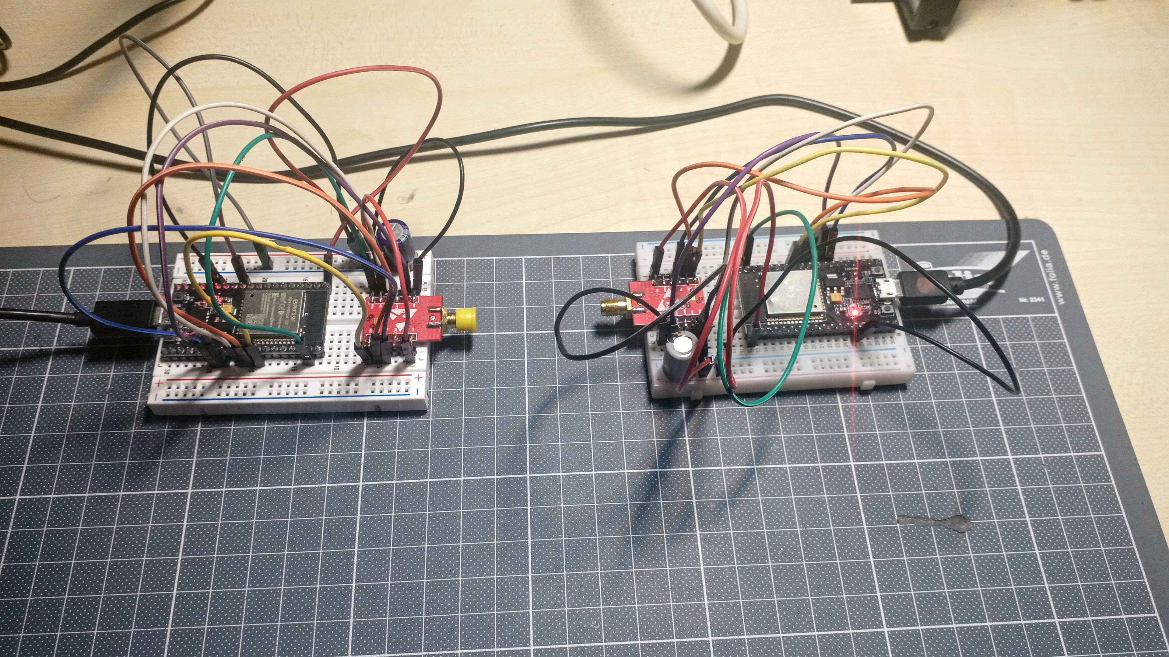
The code used is here. The client keeps sending data to the server. The server acknowledges each packet. Every 10s, the server prints out a report.
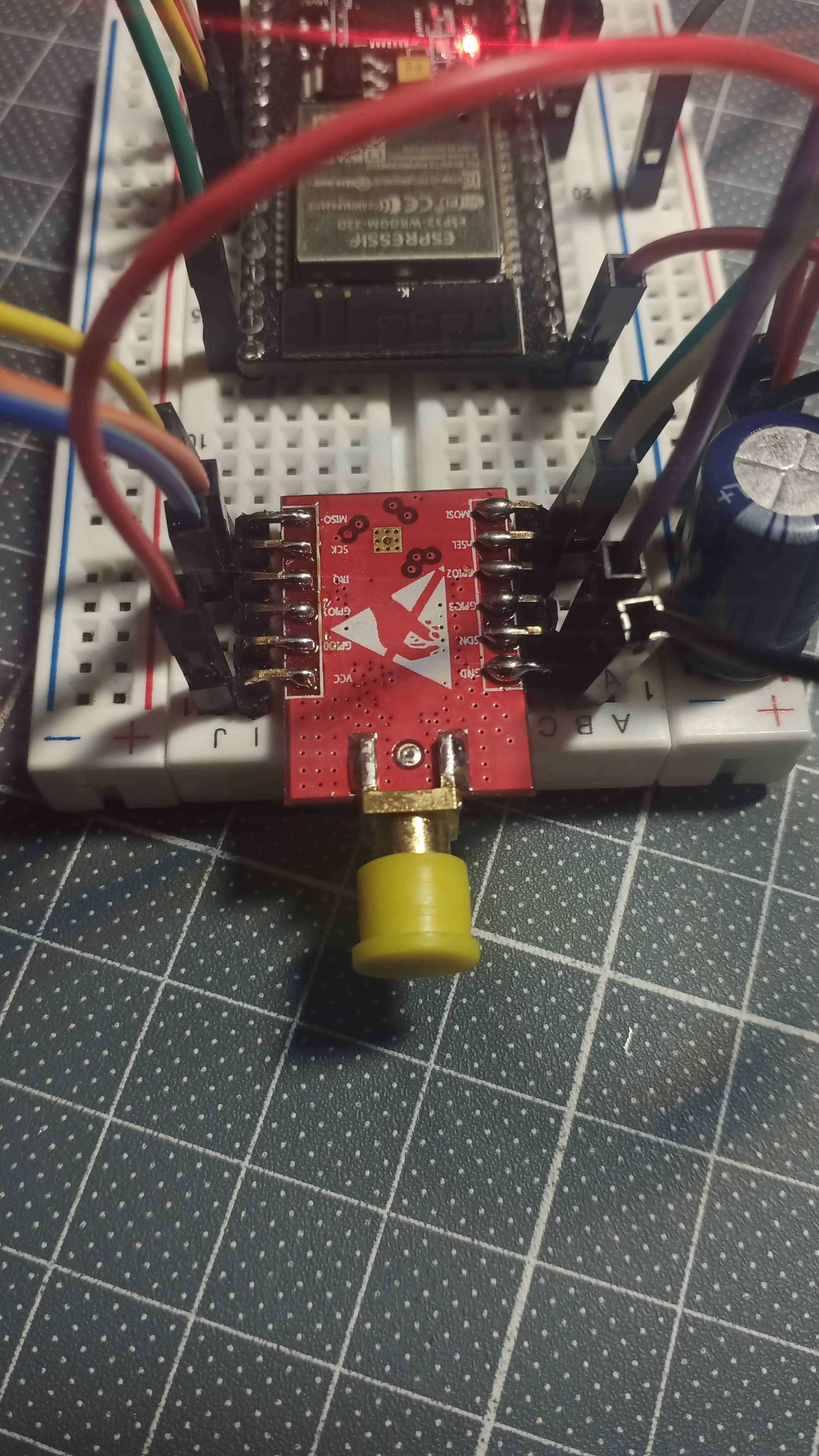
The RSSI is low because both modules are connected to a u.fl/SMA cable assembly which ends in a 50ohm load. These cable assemblies don't perform well. The signal level could be dropped further by removing the cable assemblies.
RadioHead library, reliable datagram
- Bw = 125 kHz, Cr = 4/5, Sf7 = 128chips/symbol, CRC on :
- 10 byte/frame : Total bytes : 1160 Total packets : 116 Bitrate : 928bps Average RSSI : -112.82 Average SNR : 6.78
- 30 bytes/frame : Total bytes : 2700 Total packets : 90 Bitrate : 2160bps Average RSSI : -114.97 Average SNR : 5.02
- 60 bytes/frame : Total bytes : 3900 Total packets : 65 Bitrate : 3120bps Average RSSI : -110.23 Average SNR : 7.68
- Bw = 500 kHz, Cr = 4/5, Sf7 = 128chips/symbol, CRC on :
- 10 bytes/frame : Total bytes : 4680 Total packets : 468 Bitrate : 3744bps Average RSSI : -110.21 Average SNR : 0.70
- 30 bytes/frame : Total bytes : 10200 Total packets : 340 Bitrate : 8160bps Average RSSI : -108.82 Average SNR : 1.40
- 60 bytes/frame : Total bytes : 14880 Total packets : 248 Bitrate : 11904bps Average RSSI : -108.08 Average SNR : 1.75
Spreading Factor 6 doesn't seem to work using the RadioHead library. Anyway, the throughput is rather low, taken into account that most legal options require a maximum 10% dutycycle when using such large bandwidths. The values shown here are close to 100% duty cycle.
The test has been redone using the RadioLib library. The setup is a little different. This time there are no acknowledgements. The sender uses the smallest possible delay between packets:
- BW=125KHz, Cr=5, SF7
- 10 bytes/frame : Total bytes : 2560 Total packets : 256 Bitrate : 2048 bps Average RSSI : -89.60 Average SNR : 5.97
- 30 bytes/frame :Total bytes : 4260 Total packets : 142 Bitrate : 3408 bps Average RSSI : -85.77 Average SNR : 6.25
- 60 bytes/frame : Total bytes : 5160 Total packets : 86 Bitrate : 4128 bps Average RSSI : -85.97 Average SNR : 6.47
Sending larger packets allows for larger bitrates because the overhead per databit is lower than for small packets. However making the packets six times longer doesn't yield a sixfold increase in bandwidth, because of the packet overhead.
With 60 bytes/frame, LoRa would give us more than enough throughput for the digital walkie-talkie. Unluckily to stay within the legal limits, the power output would have to be reduced to a few milli-watts.
OOK
This is simply 100% ASK. It's spectrally more efficient than FSK, but might be more susceptible to noise.
The original tests were done without data encoding (no Manchester, no data whitening), as it turned out, the OOK had a lot of difficulties receiving long sequences of zeroes. Turning on data whitening significantly increased performance.
- 4.8kbps, RXBW=6.3kHz, 60bytes/frame, data whitening on:
Total bytes : 2820 Total packets : 47 Bitrate : 2256 bps Average RSSI : -125.32
2(G)FSK
Fairly low bandwidth, more suitable for voice comms using 10kHz wide channels. Duty cycle limitations would not be needed. In these small bandwidths, FSK is quite susceptible to doppler fading when sender or receiver is in motion.
Some basics
- Frequency tolerance : a 10kHz wide band on 434MHz requires clocks that only deviate a few ppm. I used the frequency error calculated by the LoRa example to sync the clock of the receiver to the transmitter. The adjusted value is then used in the FSK code.
- Frequency deviation (FDEV) = the difference between the minimum and maximum extent of a frequency modulated signal, and the nominal center or carrier frequency. fcarrier - fmin = fmax - fcarrier = FDEV
- Bandwidth is defined by Carson's Rule : BW = 2*(FDEV+BR/2) = BR+2*FDEV
- modulation index (m)
- MSK when m = 0.5, so FDEV=BR/4
- Example MSK calculation for GSM
- Narrowband FM when m < 1
- For SX1278 m must be between 0.5 and 10
Possible ICs : SX1278/RFM98, SI4463/RFM26, RFM23, AX5243-D, AX5043, CC1101 or newer (such as the CC1200).
SX1278
Using RadioLib, a simple client server program has been made. It offers polled-operation and interrupt based operation. Using CubicSDR, I noticed a problem in the interrupt mode : the transmitter keeps its radio continuously on. The TX-interrupt doesn't occur. There were two problems. On the Nucleo32, D2 is not suited as interrupt pin. D7 is used instead. In the code, the radio should manually be put to standby mode to save power. This also clears the interrupt.
- 48kbps, freqDev=50kHz, RXBW=125kHz, 60bytes/frame
- Total bytes : 26280 Total packets : 438 Bitrate : 21024 bps Average RSSI : -93.13
- 4.8kbps, freqDev=4.8kHz, RXBW=12.5kHz, 60bytes/frame : "optimal" settings for throughput > 1200bps
- Total bytes : 2400 Total packets : 40 Bitrate : 1920 bps Average RSSI : -113.09
These were all measurements done with data whitening off. Data whitening improves performance significantly.
SI4463
Unfortunately the SI4463 is not supported by RadioLib. A closer look at the SI4463 might reveal why. There's no PDF register description. You can download some HTML-API which explains the registers. To configure the radio, there's the SiLabs WDS3 application (Windows only) that creates the radio_config header file for you.
Fortunately, the RadioHead library supports the SI4463 in its RH_RF24-class. But it's not that simple... read more on it in the 4GFSK section below.
The SI4463 is not a very popular IC for wireless modules. It's used on the HopeRF RFM26W, which is expensive on AliExpress. The Dorji SI4463 is equally hard to find.
The easiest way to use the SI4463 would be to order some HC-12 modules from the usual vendors. The STM8 on the module provides you with an AT-command interface so that you don't have to interface to the HC-12 directly. This can save you a lot of time.
I'm using the Ebyte E10-433MD-SMA module, but there are some issues with it:
- Pin row spacing is not a multiple of 0.1", so this module doesn't fit in a breadboard.
- Annoyingly small silkscreen pin labels.
- The crystal is 26MHz, while the RadioHead library is configured for a 30MHz crystal. RadioHead's initialization procedure works, but the module doesn't transmit or at least not on the correct frequency. The SiLabs WDS3 program is needed to generate a header file that matches this module. After creating that header file and including it, the SI4463 finally works.
Frequency offset : device 1 : 433.99505MHz, device 2 : 433.99300MHz. So the difference between the two is about 2kHz (or 4.7ppm). The SI4463 has an AFC which can correct up to 160kHz of frequency difference. The preamble must be long enough for the receiver to "sync" on that signal.
- NiceRF RF4463F30
- +30dBm output
- Bands: 142–175, 283–350, 420–525, and 850–1050 MHz
- 64byte FIFO
- data whitening
- €17.22/2pcs, free shipping
- HopeRF RFM23BP
- +30dBm output
- Bands: 413-453, 848-888, 895-935 MHz
- 64byte FIFO
- data whitening
- Some drawings in the datasheet are copied from the SI4463. Is HopeRF using SI4463 ICs?
- €7.04 + €3.13 shipping + €0.59 (shield) + €1.09 (shipping for shield)
- Ebyte E10-433MS1W
- +30dBm output
- 425~525MHz
- very little documentation: 26MHz is probably a crystal, not an oscillator. What is the revision of the SI4463 inside? The GPIO pins to control the PA are described in some app. note.
- €5.75 (free shipping)
4(G)FSK
4GFSK vs 2GFSK & Calculation of the modulation index for digital frequency modulation
- modulation index m (innerdeviation is frequency difference of the two used modulating frequencies):
- 2x more spectrally efficient modulation than 2GFSK.
- For the same data rate and modulation index, 4GFSK has about 2dB loss in sensitivity with respect to 2GFSK.
- inner deviation = outer deviation / 3. For the same data rate the bandwidth is halved, so the inner deviation for 4GFSK is only 1/6 of the frequency deviation of the 2GFSK. This corresponds to a 5dB loss (depends on modulation index).
- Halving the RX bandwidth for 4GFSK reduces noise power in the modem by 3dB.
Possible ICs : SI4463, AX5243-D (SPI, no single ended antenna output, so can't be used with external PA), AX5043 (SPI interface), CC1101 (or newer).
SI4432 is obsolete. The OnSemi AX5243-D is not available on a 500mW - 1W module. The SI4463 should have a much better ACS (Adjacent channel selectivity) than the SI4432 or the CC1101.
The CC1101 module also has a high power version from EByte. RadioLib library doesn't support 4FSK (yet).
AX5043 looks interesting, but little tools are available. There's a home brew radio however.
SI4463
breadboard setup (4GFSK, 2.4ksps (=4800bps), 350Hz inner deviation, RX BW autocalc, -32dBm TX power, 60bytes/packet, 160ms packet interval): finding minimal RSSI for 0% packet loss:
Total bytes : 3000 Packet loss : 0% Bitrate : 3000 bps Average RSSI : -96.98dBm
It's quite disappointing that the RSSI is only downto -97dBm. According to the datasheet -110dBm should be possible. The least we can say about the breadboard setup is that it's far from ideal. It's still far off from the -118dBm specified by commercial PMR446 devices.
WiFi
I'm not planning to use wifi in the final application. It's only a proof of concept. If you want a VoIP solution that you could really use in your application, have a look at Mumble. It's used in the RigPi.
TCP
- wireless_mic_TCP : a server is connected to an audio source. Clients can connect to this server and output the received sound to an audio sink. One way transmission only. In contrast to the example it was based on, this implementation is fully non-blocking.
- wireless_2way_audio_TCP : simultaneous 2 way audio system. Voice-intercom over TCP-connection. A very simple VoIP application in some way.
- wireless_2way_audio_TCP_codec2 : the same application as above, but transferred data is first encoded with codec2.
Discussions
Become a Hackaday.io Member
Create an account to leave a comment. Already have an account? Log In.