 NotBlackMagic
Analog Input Noise
During the last few weeks, using the PC Acquisition Software, the analog input noise was analyzed. For now only of the Analog Black A but the values should be the same as the hardware and layouts are the same. To get the baseline noise level one analog input channel is configured in differential mode and its inputs are shorted. The standard deviation of the acquired ADC samples is then calculated, this gives us the input noise in ADC counts. In this test scenario a standard deviation of bellow 2 counts was measured, for all ranges and sample rates.
To get an idea of cross-channel interference the same test as described above is performed, but this time a full range noise signal is injected into an adjacent channel. The output of this scenario is shown in the figure bellow, showing a screenshot of the PC Acquisition Software Window. The noise/standard deviation is bellow 3 counts on the tested channel, in green. The noise signal is visible in red.
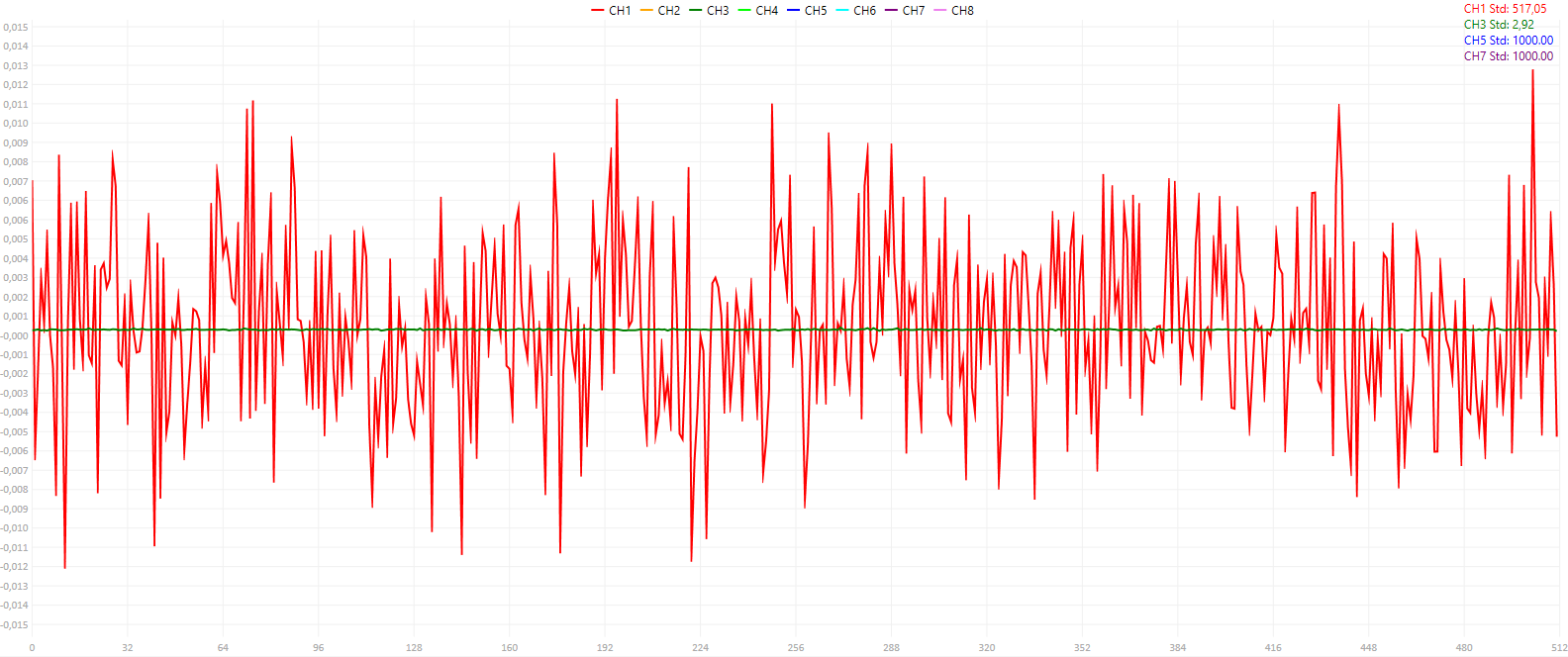
Overall, in all tested scenarios, ranges and sample rates, the standard deviation was always bellow 4 counts which means that the DAQ has a worst case effective resolution of 10-bits.
PC Software
As seen above, the PC Acquisition Software is now functional but with a lot of limitations. It is capable of configuring both the Analog Inputs and Output of the Analog Block A. The Analog Input acquisition window refresh rate is very low, only refreshed every 1s, but the PC DAQ driver receives and saves the samples in real time without problems. The limitation is on the Graph Drawing, which needs to be optimized.
The Figure bellow shows the PC Software with the Analog Input Menu open. The signal shown is generated by the Analog Output channels 1 and 2 and is acquired by the Analog Input channels 1 and 3, using the settings shown in the figure.
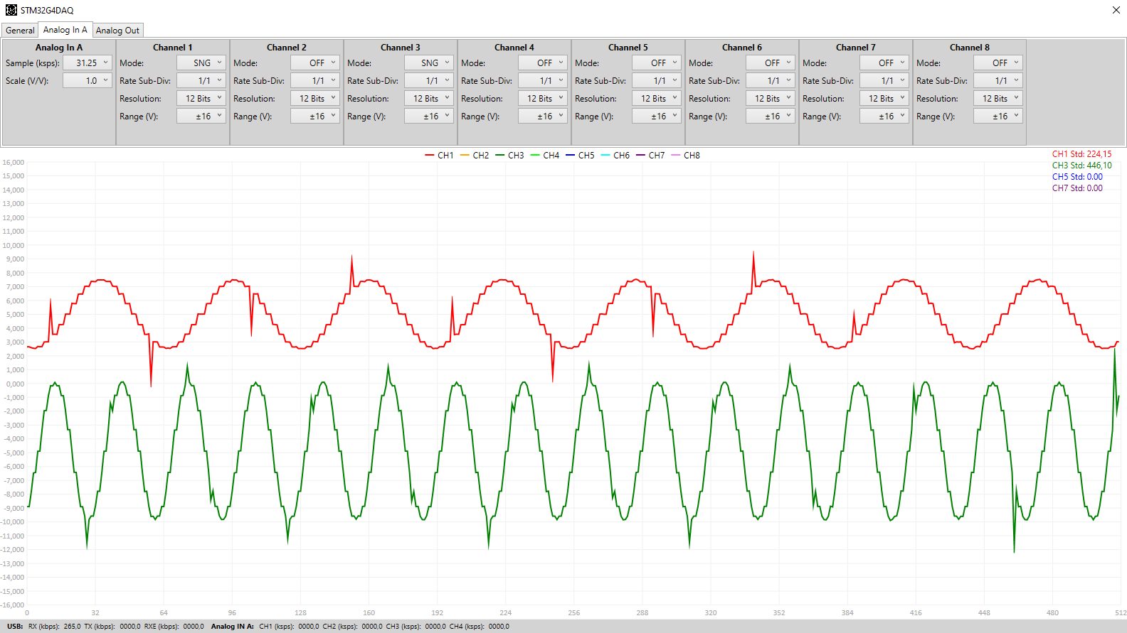
The Analog Output signal generation can, for now, only generated DC signals and sine waves with 20 sampling points, as can be seen in the figure bellow. Also, at high sample rates, the acquired signal sometimes has the spikes seen in the figure above. It is not clear yet what is the origin of them...
The PC Software is available on my GitHub page.
For more information and more in-depth explanations visit the website. I also sometimes publish sneak peaks and pictures of project progress on both Instagram and Twitter.
Discussions
Become a Hackaday.io Member
Create an account to leave a comment. Already have an account? Log In.