 Tom Mladenov
Raspberry Pi SDR Cyberdeck
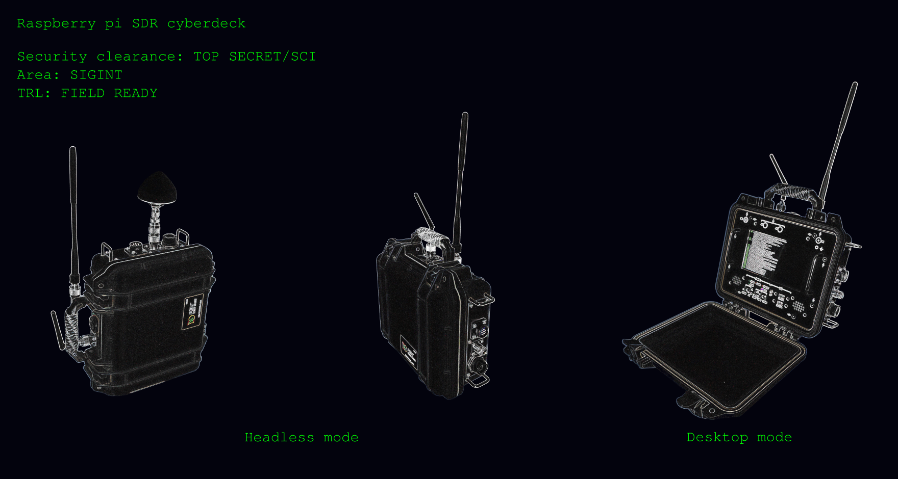
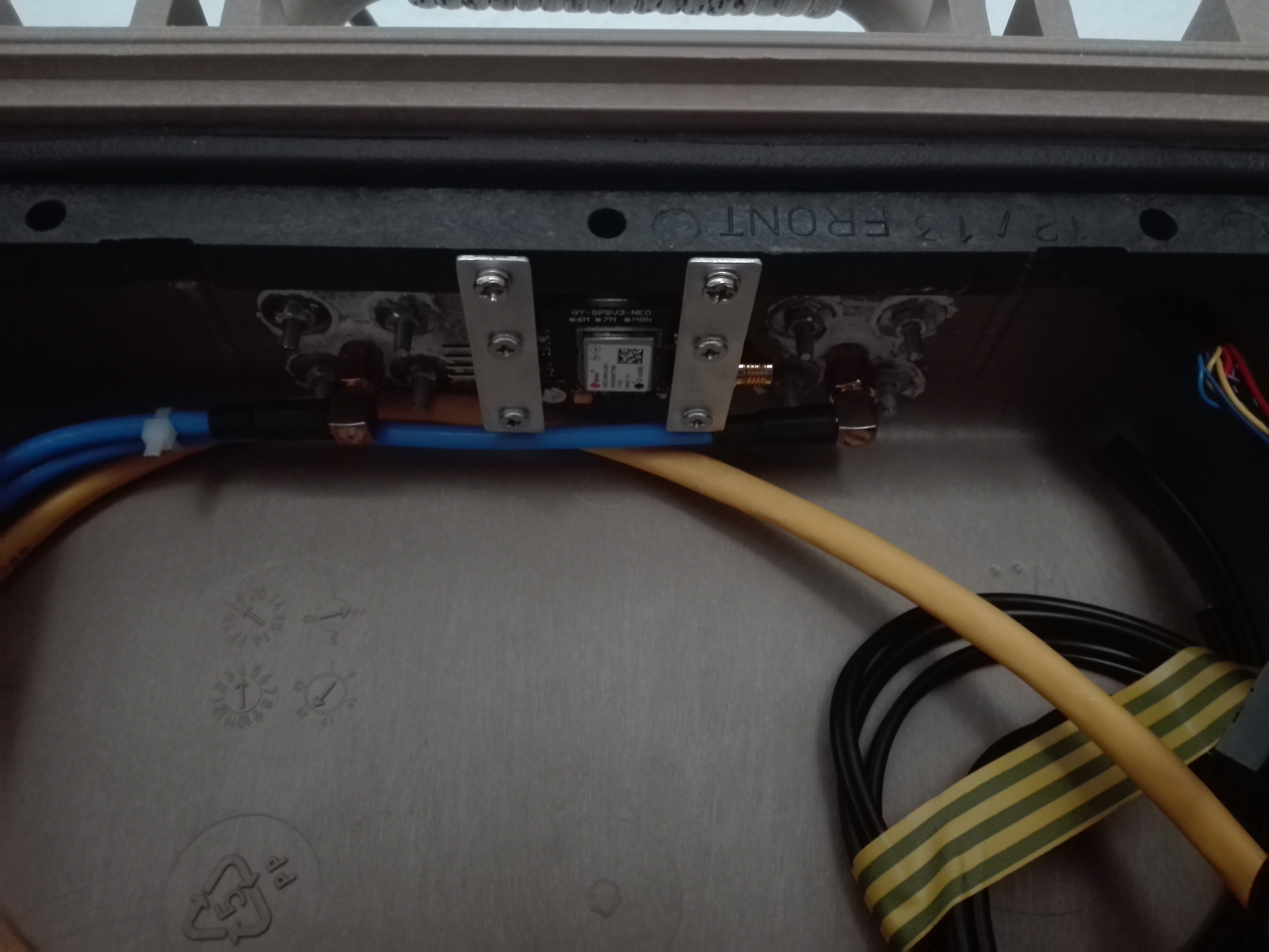
The SDR Cyberdeck is a self-contained unit that allows the operator to adapt to any operational situation where RF monitoring is required. It features built-in GPS, dual channel Software Defined Radio, Real-Time clock, audio system, internal batterypack offering 8+ hours autonomy at normal usage, remote operation via an HTTP REST API, web dashboards for sensor telemetry, VNC for remote control and more...
Hardware
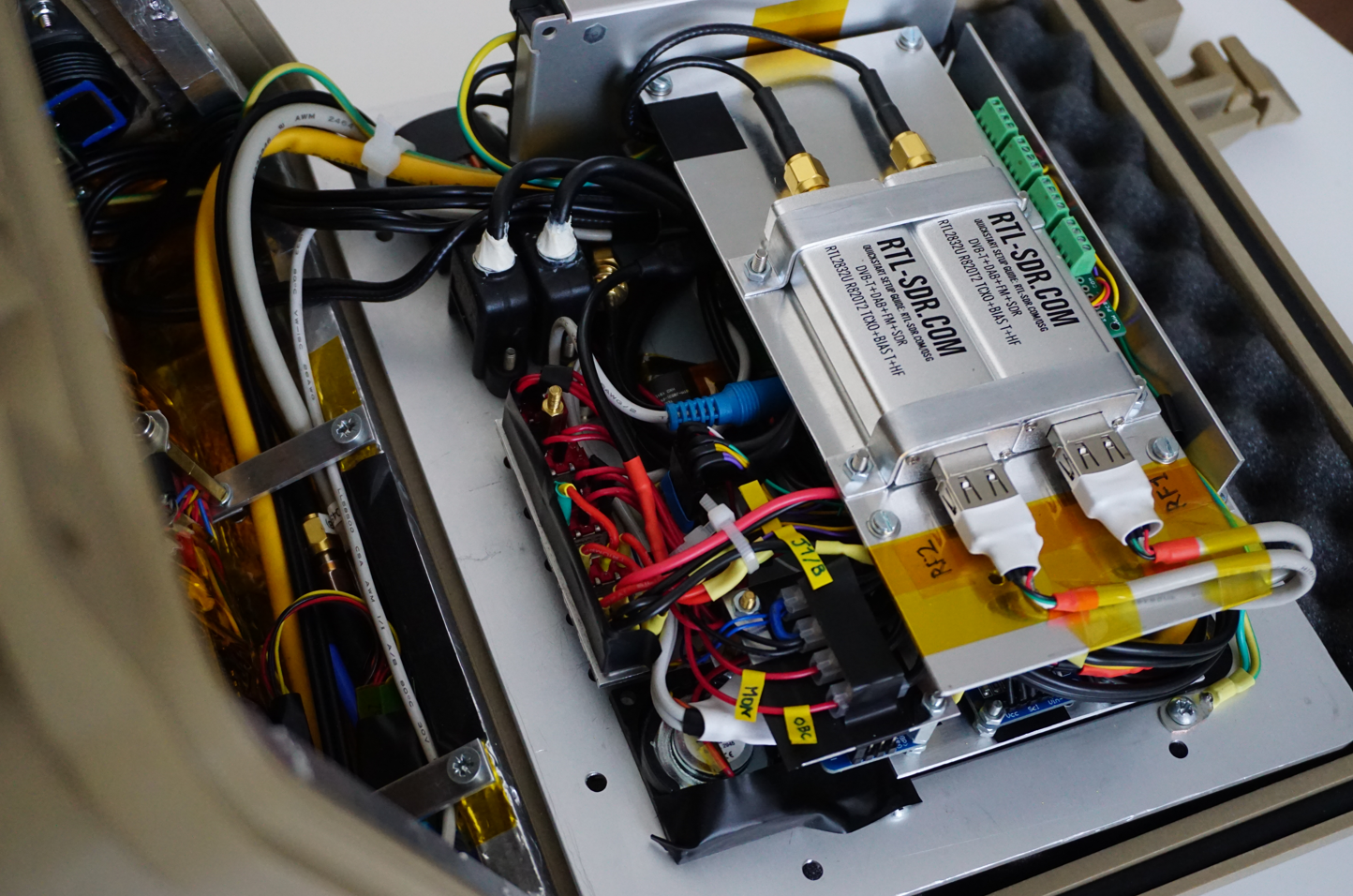
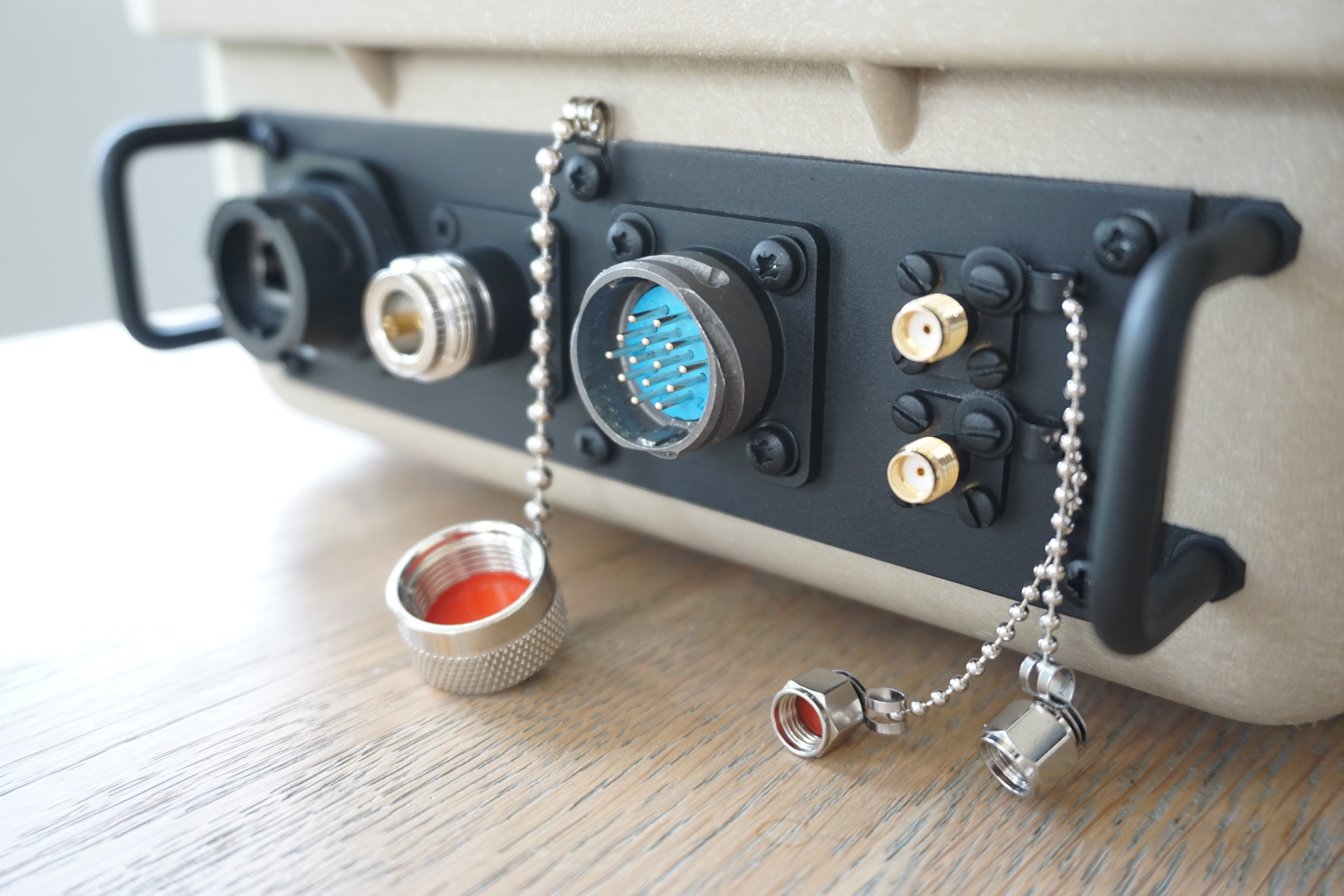
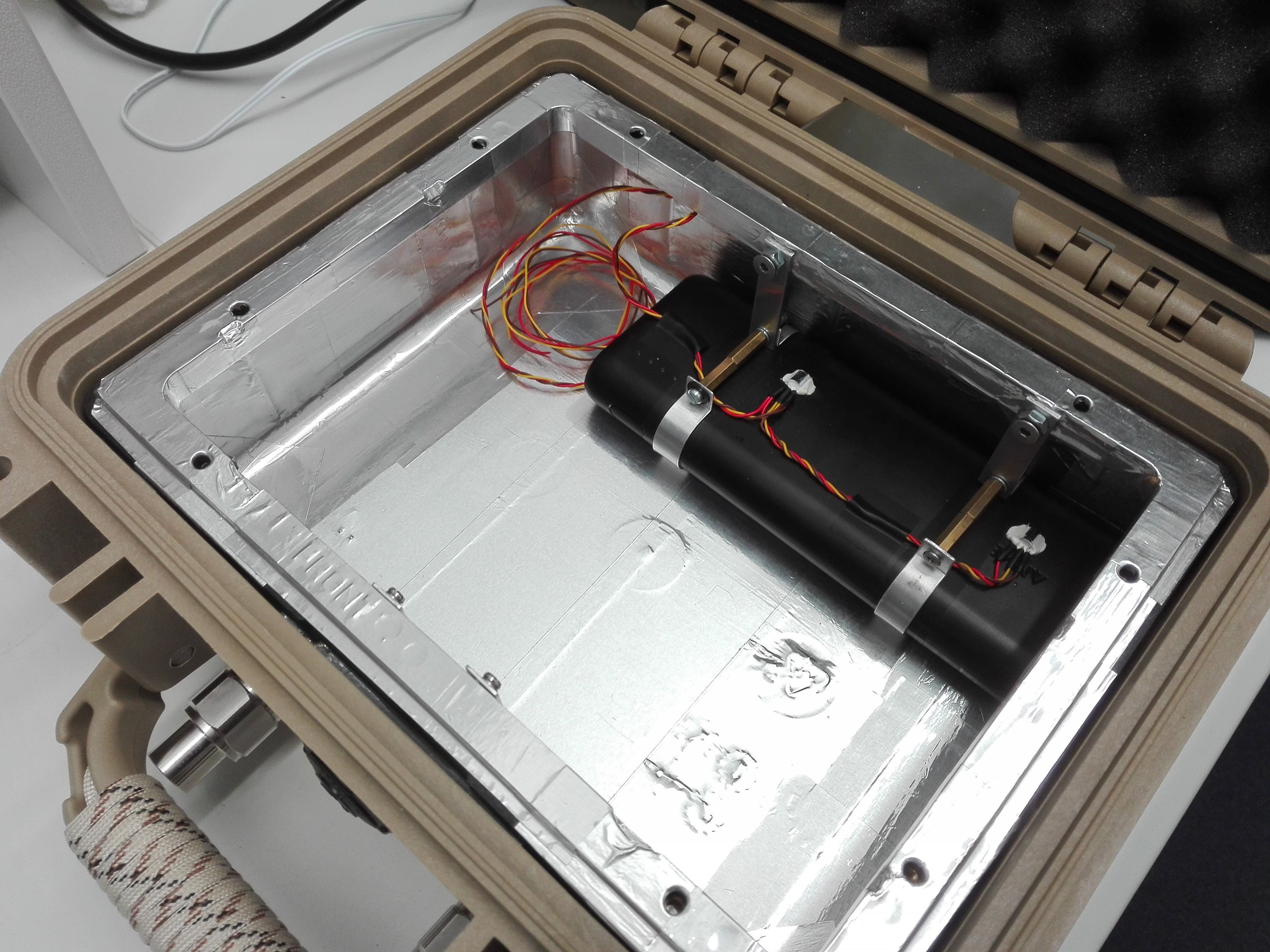
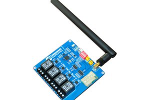
The HW is based around a Raspberry Pi 3 Model B sandwiched between passive cooling elements and a stack of dual Software Defined Radios (SDRs) and power switching, routing, signaling and a small audio system consisting of 2x 3W frontpanel speakers that is driven by the RPi audio 3.5mm jack output.
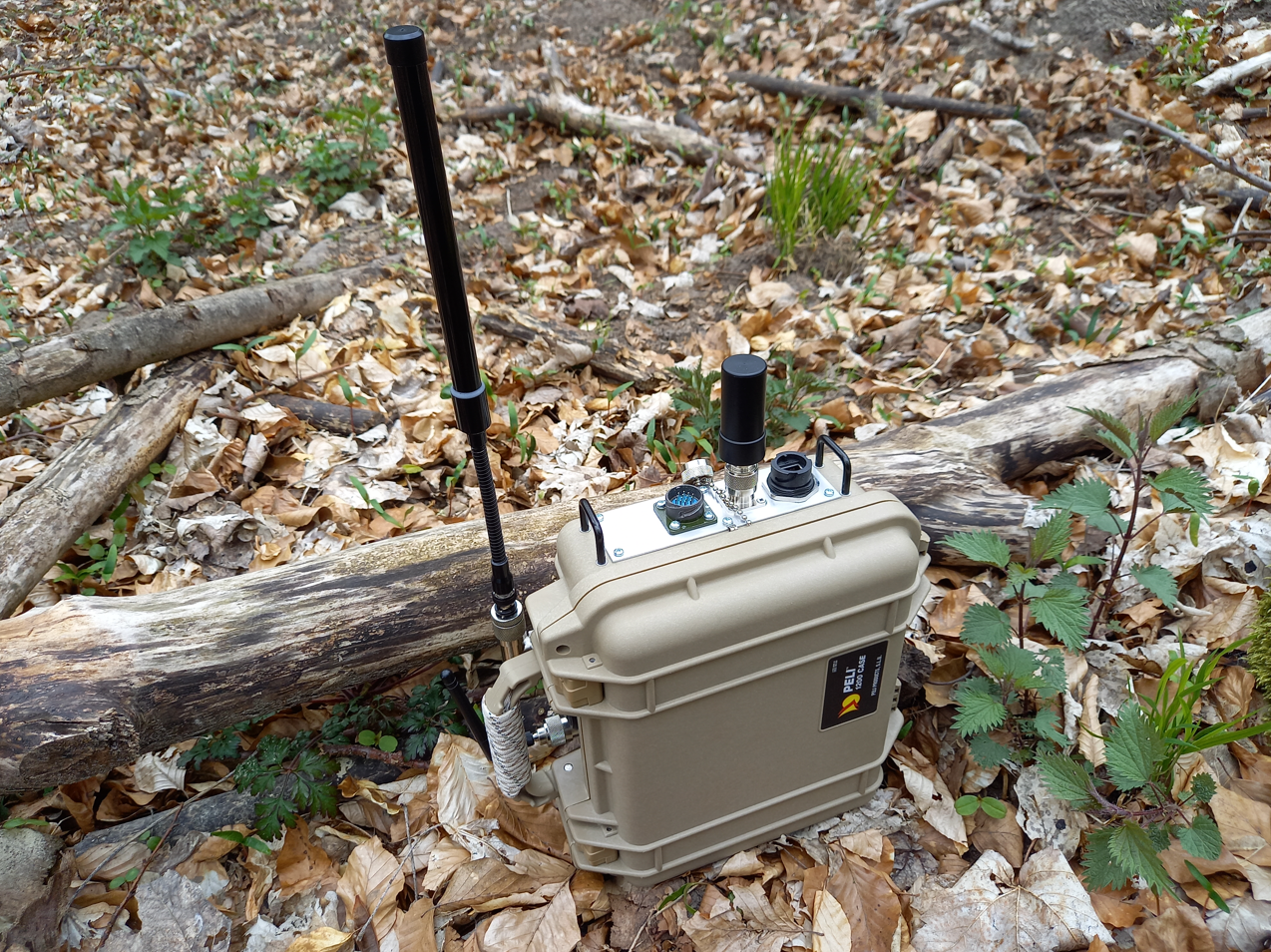
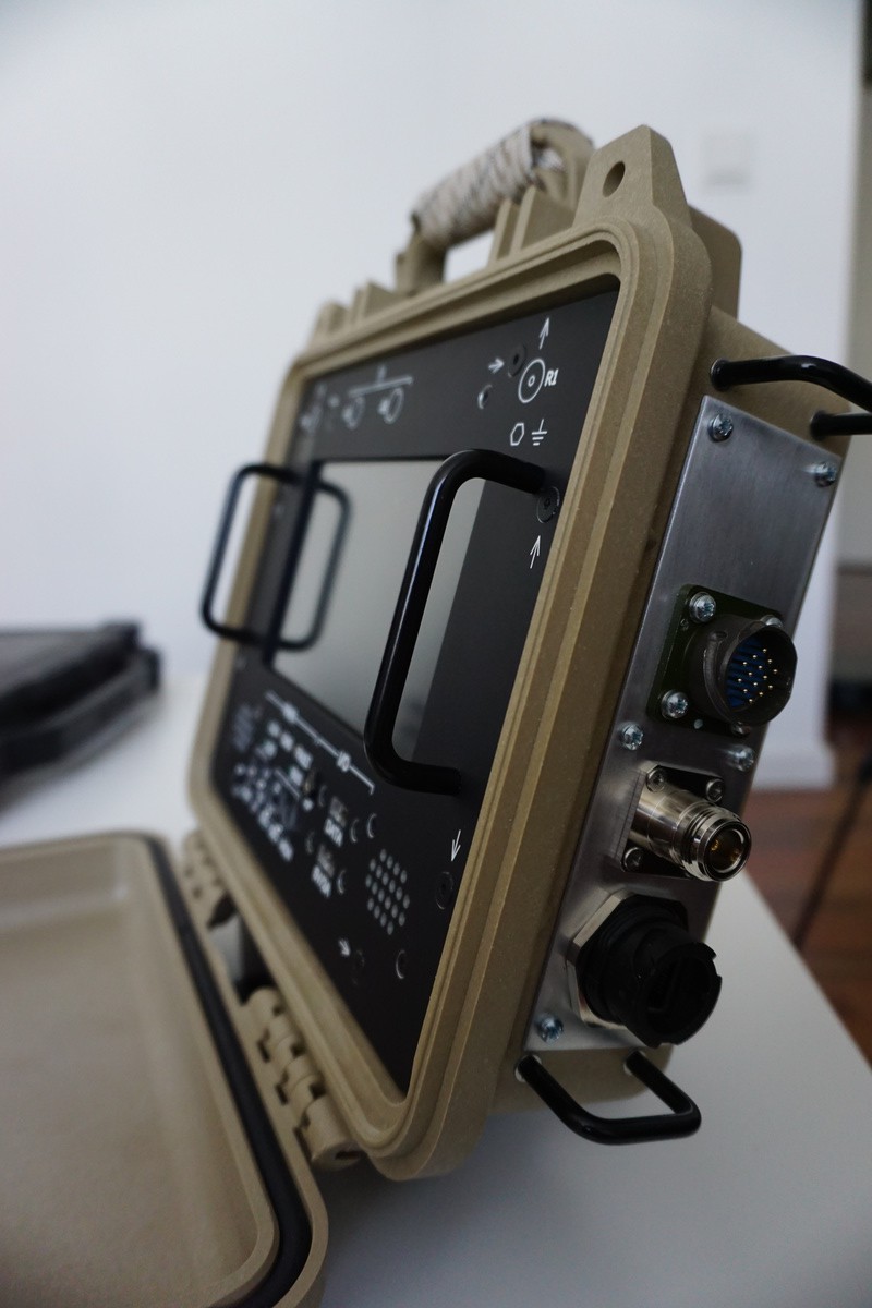
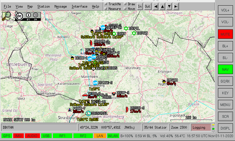
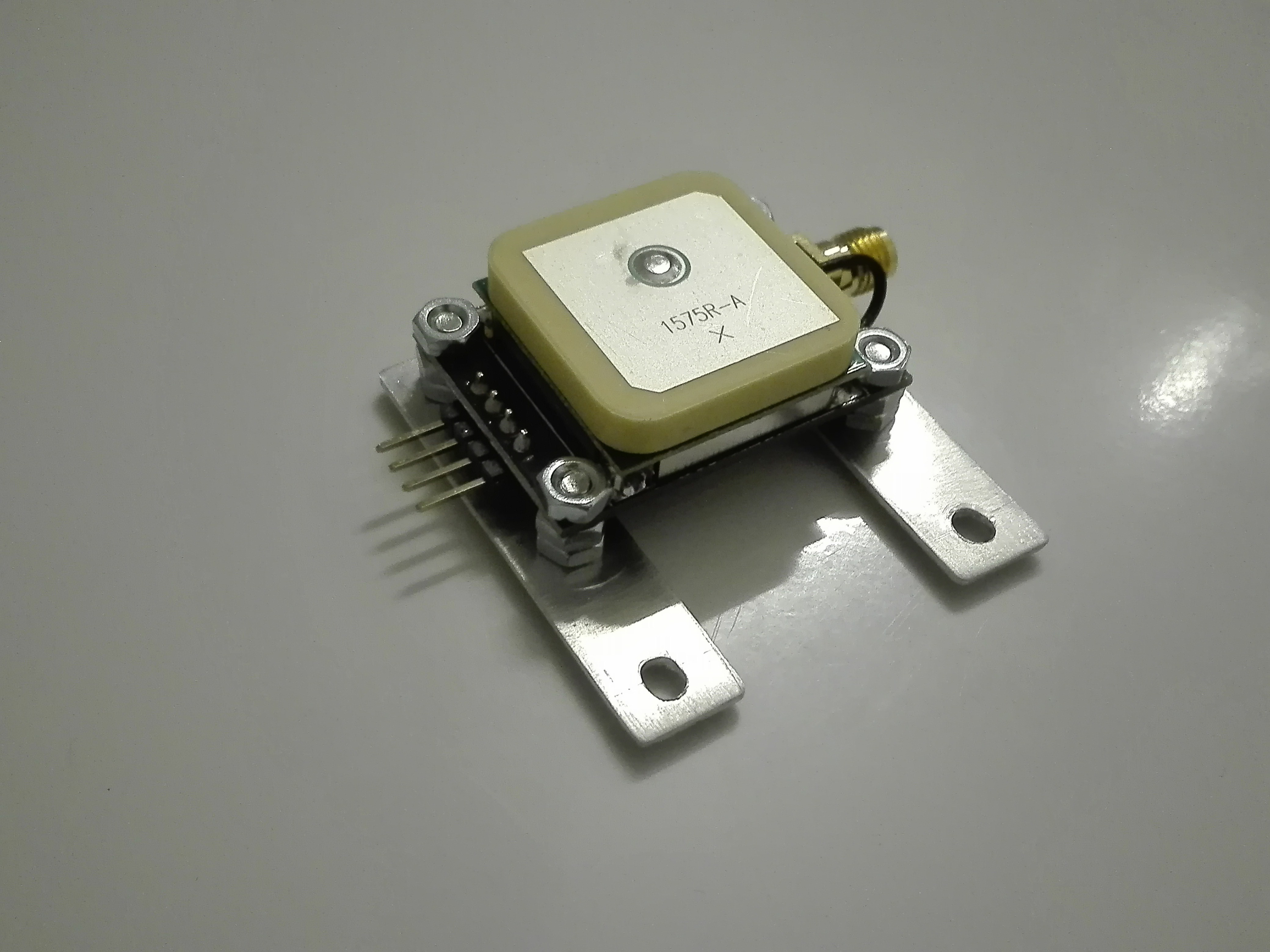
Unit shown in operation below during RF monitoring and surveillance of forest area during training operations. Left antenna is general wideband coverage, smaller stub antenna is an active helix GPS antenna.
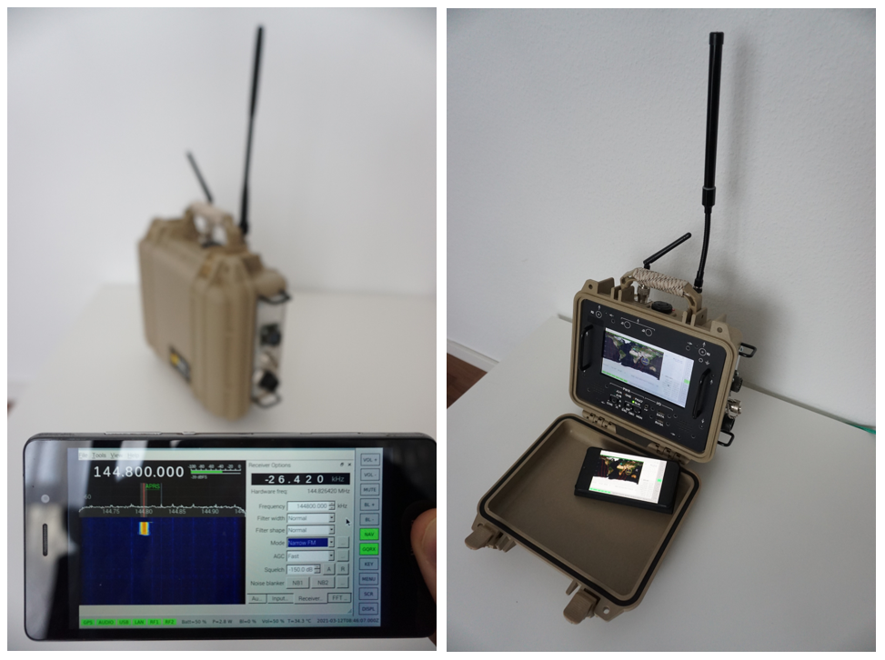
Headless mode:
Spectrum monitoring in headless mode (left), desktop mode with shared session available on remote device (right.)
Software
The Raspberry Pi SDR cyberdeck runs on a software framework with at it's core an ASGI (Asynchronous Server Gateway Interface), in this case uvicorn. The ASGI interface connects to FastAPI which performs the function invocations in the Python threads which control the Devices, Processes and Applications. This allows for easy system manipulation via HTTP1.1 GET/PUT/POSTS methods. The Python threads controlling the processes can range from a commandline decoder to decode APRS via an audio interface, through to starting a VNC session or starting navigation/mapping software. The intention is to make complex application flow, configuration and control easily accessible via the Cyberdeck API interface (which performs HTTP requests to the server), therefore eliminating local commandline interaction with the system. In parallel system data is dumped to an influxdb database, and exposed via Grafana, allowing easy system monitoring over longer periods of time.
The software is still in development and actively maintained at is hosted at GitHub.
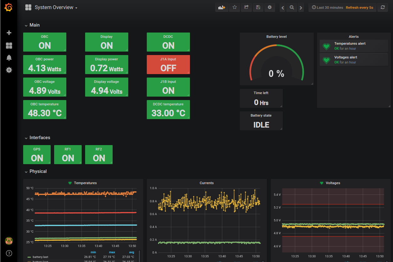
Remote Visualisation
Grafana serves as the entrypoint for any remote visualisation over longer periods of time, or general status monitoring. It can be used to view currents/voltages/temperatures and the status of different peripherals.
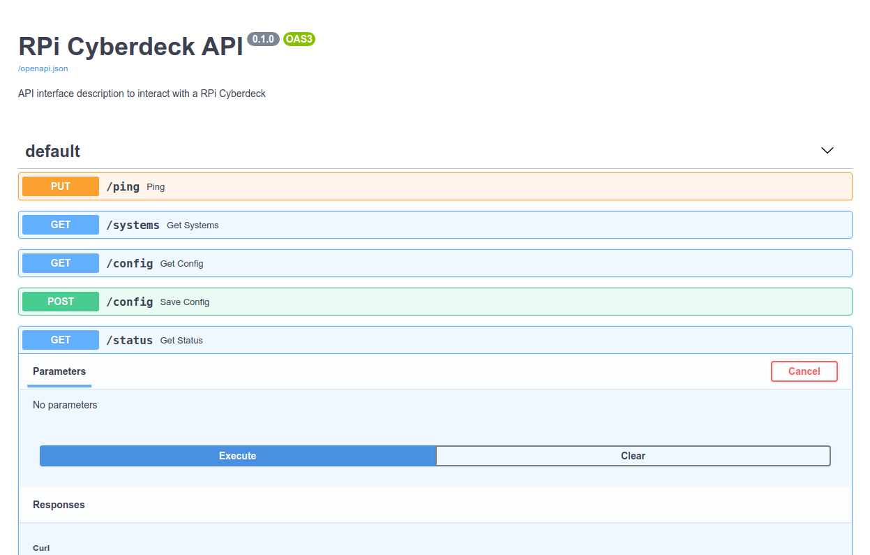
Remote Documentation
FastAPI has a handy feature where it serves an easy-to-use test interface on http://x.x.x.x:5000/docs. This can be used to test out methods and check if they have the desired effect on the system.
RCC
The remote control client is a simple Python application which uses PyQt5 and grid widgets which get populated based on the structured JSON data that is received via the Cyberdeck API. From this interface, devices can be switched on/off, status monitored, etc...
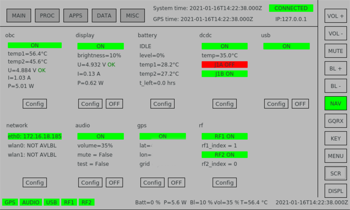
The native size of the GUI is intended for use on the Official Raspberry pi 7" touchscreen.


 Jorge Miar
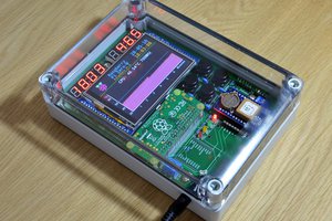
 Frank
Frank
Great looking project, instructions and even a RaspberryPi image that has all the software and configurations would be greatly appreciated.