 agp.cooper
Checking the Circuit
Here is the original circuit diagram:
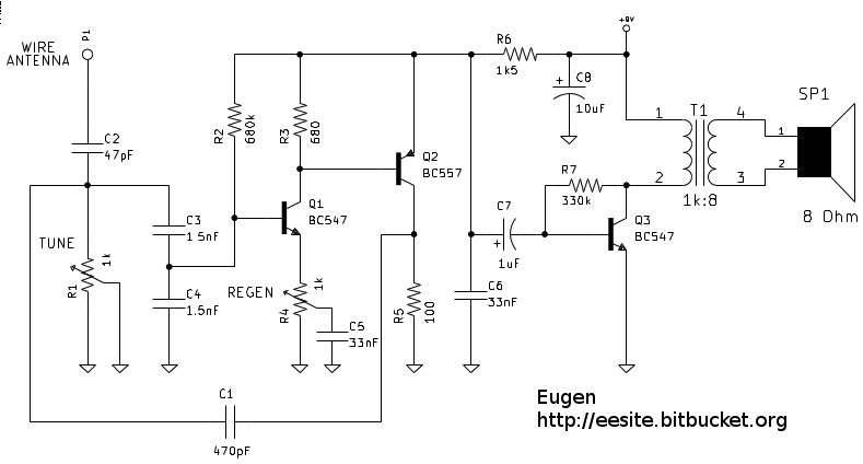
(source: http://eesite.bitbucket.org/html/electronics/wien_regen/wien_regen.html)
I built a simulation of the circuit to confirm that it works, and yes it does.
Here is the frequency analysis for the Regen control setting varied between 20% and 50% (and with the Tune control at minimum (lowest frequency)):
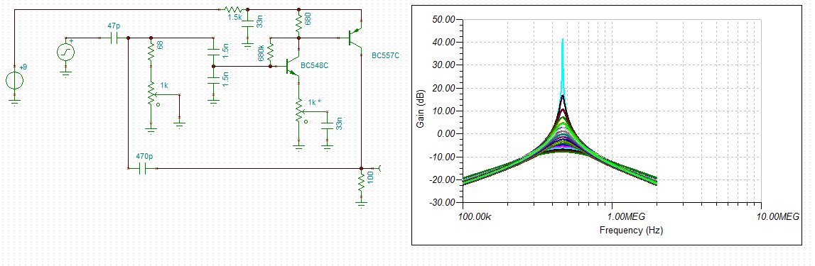
The transient analysis indicates that after the circuit begins to oscillated it builds up slowly with increase in Regen but at some point becomes chaotic, and then goes into audio (pulse) oscillation (squealing).
The Regen setting is sensitive to the input signal.
The DC voltage across the 100 ohm resistor is about 200 mv which limits the oscillation voltage to 10s of mv.
Unlike conventional Wein Bridge oscillators, the single Tune control means the Regen control needs to be readjusted.
Audio Recovery
The simulation does show audio coming out of the collector of T2 but roughly equal to the modulation level.
Thinking about how this works I assume the oscillator locks onto the input frequency and is basically a synchronous detector (autodyne detection).
If this is the case then it has to oscillated to detect a signal.
Here is the strip-board layout:
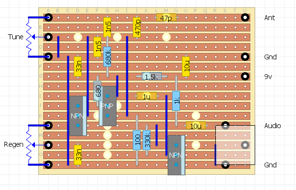
Note I have not used an audio matching transformer.
This is a mistake as the squealing when the circuit goes into audio oscillation is quite loud (in an ear-piece).
Results
With a short aerial (and no audio transformer) and no ground, I could just make out a local station when the receiver is oscillating. The higher the oscillation the better the audio (until it breaks down). No audio without oscillation.
But overall my version of this radio would be considered unusable.
The author's version is quite clever in it's design but I suspect the video is about as good as it can be (remember this is a MW receiver):
Wien Bridge Receiver with a better Antenna
I decide to hook up the Wien Bridge receiver to a better antenna.
Well the Wien Bridge liked that!
With a reasonable signal, the circuit has a bit of regenerative/autodyne hysterises.
I will have to investigate this circuit further!
The Notch Network
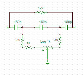
The Wien bridge network could be replaced with another network (e.g a Twin T) that may have better (separated) controls. I found a Hall (notch) network that looks perfect:
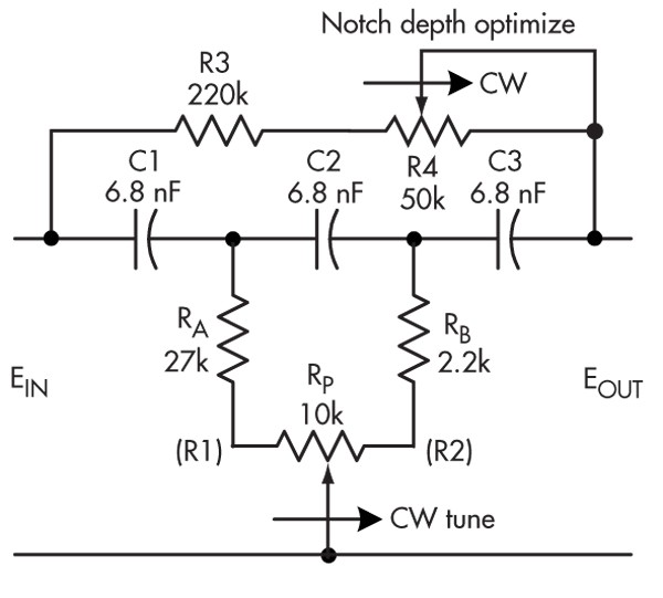
(source: http://electronicdesign.com/analog/rediscover-truly-tunable-hall-network)
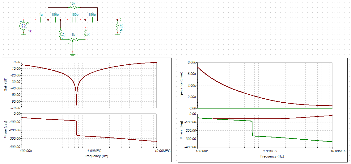
Here is a MW tunable (notch) network :
I thought I would check the network input impedance. The simulation says about 2.2k ohm:
Next I have to workout how to turn this into an oscillator. Here is an OpAmp oscillator:
 (source: http://electronicdesign.com/analog/rediscover-truly-tunable-hall-network)
AlanX
Discussions
Become a Hackaday.io Member
Create an account to leave a comment. Already have an account? Log In.