TheMixedSignal
How this project came to be:
Build video:
This project was really fun, and kind of evolved in a very rambling sort of way. It started off in a completely different direction - the plan was to get a reed-based instrument working. At some point, I actually got a saxophone reed to work with a 3d-printed mouthpiece... just barely! And with a 5 foot piece of PVC, it made for a pretty interesting almost-didgeridoo-like sound. After some tweaking, I finally got a fipple to do that, too (in the build video).
Getting a fully functional PVC reed instrument is still a goal of mine, but for the time being, I decided to try out 3d printing a fipple and making a fipple flute. The first working iteration of that fipple is featured in the Cream Cover I did last month:
https://www.youtube.com/watch?v=VaGBY9zagCU
Long story short, this ended up becoming a slide whistle to change notes. It became apparent that I could re-use some code I had from the last project I did back in May-June 2020 (A "Semi Manual Electric Rail Kalimba" aka the SMERK), and that was a huge plus.
So enough of my rambling - here's the design:
Design Overview
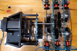
Design philosophy is to use relatively cheap/easy-to-acquire parts like those used for 3d-printers (centrifugal blower fan, 8mm linear rail), and 3d-printed + laser cut components.
Hardware/mechanical design was all done in Fusion360. Some things that required optimization and iteration were:
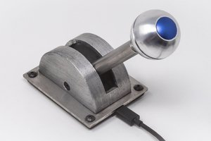
- the fipple (part of the whistle that air is forced through). I made a blown up and cross-sectioned version for explanation in the upcoming build video(s)
- the height and size of the pinion gear/motor mount subassembly (too large a gear = too much torque for motor)
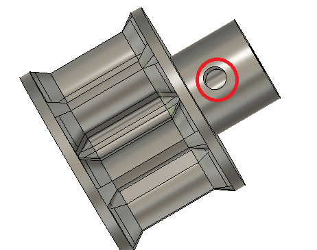
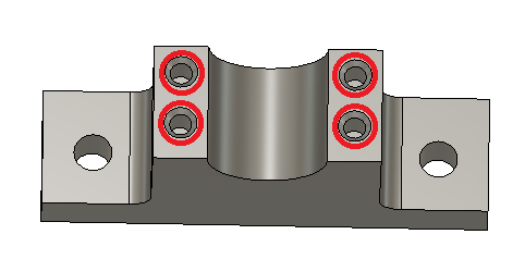
- the fit of the O-Ring/8mm-rail Assembly (there's a tiny 3d-printed part there that holds the o-ring, whose diameter took some time to optimize, and it's still a bit too tight)
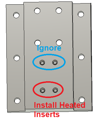
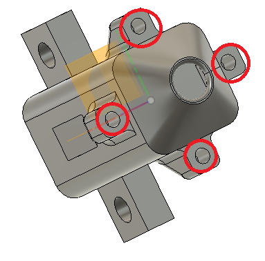
The design uses a lot of M3 heated inserts and 1/4-20 screws/tapped holes... mostly because I have tons of these. [Achievement Unlocked: Imperial and Metric in Same Design.]
Firmware and Electrical Hardware:
The microcontroller board used is the Arduino Due with a CNC Shield v.3 w/ A4988 drivers. This combination is a favorite of mine for getting MIDI + USB + NEMA17 Stepper Motors going quickly.
The stepper motor is a 2A NEMA17 from STEPPERONLINE.
The microstepping configuration is set up to 1/8th microstepping. This provides a decent balance of speed and quiet.
The firmware is sort of a rough/ongoing sketch for the Arduino Due. I see this as sort of a quick, but generic "correlate some subset of MIDI to a stepper motor position". It uses some dead-waits that I'll eventually design out, but for now it seems to do the job.
Warning: some variables are named for a similar project I have going (Semi-Manual Electric Rail Kalimba, so apologies for the "kalimba" and "flute" inconsistencies). The firmware is configured to use the Y-Axis of the CNC shield as I've got some ongoing work on the X-Axis for controlling another instrument simultaneously (will post that project soon, I hope). The code here relies on the Arduino MIDIUSB Library, which is a very simple way to get a class-compliant MIDI USB device working through the Due's Native USB port.
A pre-processor Macro "#define" for isTuning exists. This enables the user to tune the instrument. Connect via the programming USB port and type a number of steps. Use those numbers to populate the "pulleyPositions.h" definitions.
Fabrication
- The base-plate is laser cut (.dxf's) on 1/4" clear plastic
- Most other components are 3d-printed
- 1/2" ID PVC Pipe is cut to appx 400mm in length
Some notes on this project:
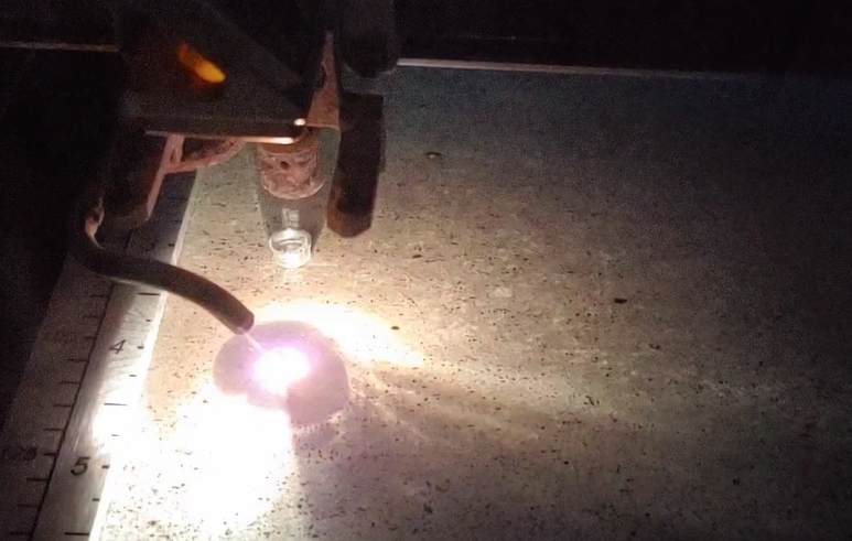
This project requires laser cutting, installing heated inserts w/ a soldering iron, 3d printing and some tuning in...
Read more »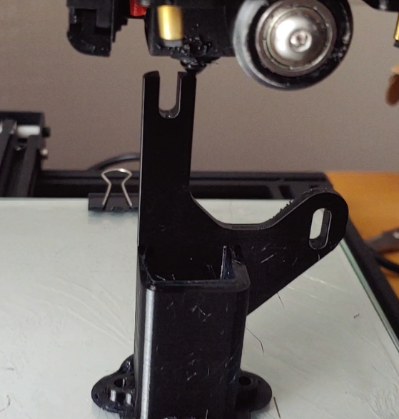
 zapwizard
 Sam Baker