 Allen Kreager
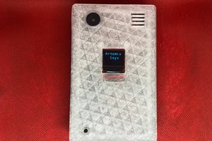
The transmitter is powered by a Teensy 4.1 microcontroller and communicates via an nRF24L01 module. It has four primary analog input “channels”; steering, throttle and “X” and “Y” from a PSP thumbstick. It will have other inputs from pushbuttons, toggle switches, and probably a rotary encoder and/or potentiometer knob. Finally, because no project is complete without just a little feature-creep, I also added an Adafruit touch TFT.
I used two different 3D scanning methods to create reference geometry to use while designing the transmitter body. For the first method, I used a Microsoft Kinect v1 to scan an old RC transmitter. This method gave merely passable results as the Kinect sensor is not suited to scanning small objects like this. For my second attempt, I used the photogrammetry software Meshroom to create a scan of a computer flight stick that had a better layout for all of the input methods I had planned. Since I was only planning on using the scan as reference geometry, this method worked perfectly with very little mesh cleanup.
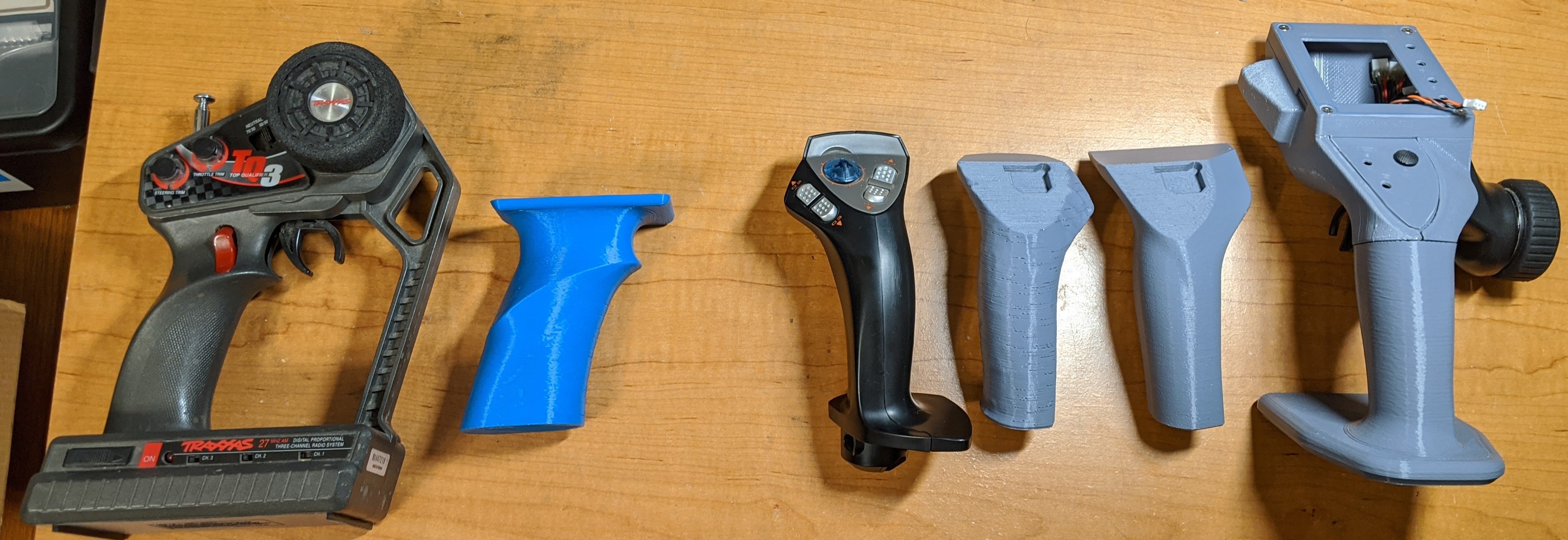
I brought both scans into my CAD program (OnShape) and mocked up the grip geometry to verify size and feel with a few 3D printed prototypes (above). From there I continued modelling the rest of the transmitter assembly until I had a place for all of the various modules and components necessary. This included the throttle and steering assemblies harvested from a FlySky GT3B transmitter. I modeled these parts by measuring the components with calipers and verifying size and shape through many 3D printed prototypes. At this point I decided to make a full prototype of the transmitter assembly to verify ergonomic placement of all the components. I divided the body into smaller sections to fit on my 3D printer and to improve printability. Everything printed well without any supports and after a couple hours of finishing and assembly I had my first prototype!
I am planning on designing a few PCBs for the transmitter. The primary one will break out the Teensy pins to individual JST ports for each of the inputs and the display. The secondary board will likely just have momentary push buttons for the inputs. And a final board for power.
The code at this point is pretty basic, mostly copied from a few examples I found around the web. The receiver electronics consist of an Arduino Mega connected to another nRF module and a BasicMicro Roboclaw 2x30 motor controller in packet serial mode. The most notable feature of the code is using the acknowledge payload function of the nRF24 library to return information from the Roboclaw to the transmitter. Currently I am returning the main battery charge, Roboclaw board temperature and instant amp draw from each of the motors.
Planned Features:
I need to add a calibration function for the analog inputs and an M-Stop bit to be sent to the receiver.
I want the transmitter to be able to control multiple remote vehicles without changing the code for each new receiver. I am hoping to do this by having something like config files stored on a micro sd card in the teensy with the unique parameters for each vehicle and a menu on the touchscreen to select between them.
I also need to vastly improve the touchscreen code:

 Dillon Nichols
 Phil Malone
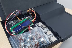
 Craig Hissett
 Boian Mitov
how did you model the hand grip part, did you do any physical prototyping like with clay or just guessed curves? looks pretty good