 Paul McClay
(update: add note to Structure:Alignment)
Here's an attempt to describe some of what makes this extremely low cost sub-mini CNC mill work. Hopefully having it somewhere to refer to will simplify writing more about how to make one for yourself!
Axes

This idea for a cheap, compact, and usefully functional linear slide seems to work pretty well.
The following photos of a simple unit made to test the idea show the basic configuration. (please pardon the fake rods - they're just for the pix)
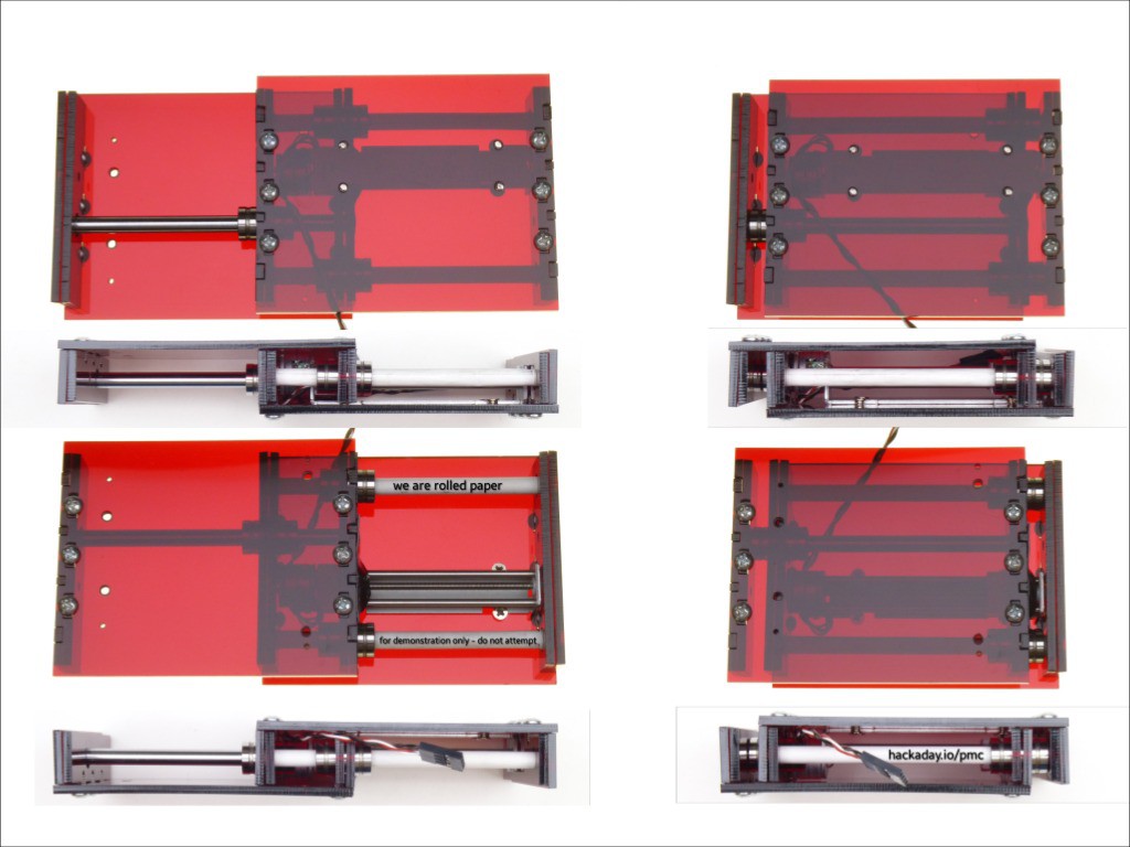
The stiffness of the telescoping configuration varies through the range of motion. The diagrams below show the triangle supported by the three bearings in green and the favored loading area in blue. Assuming the "bottom" half anchored and the "top" half in motion, the left & right photo pairs show how to orient the unit for different applications.
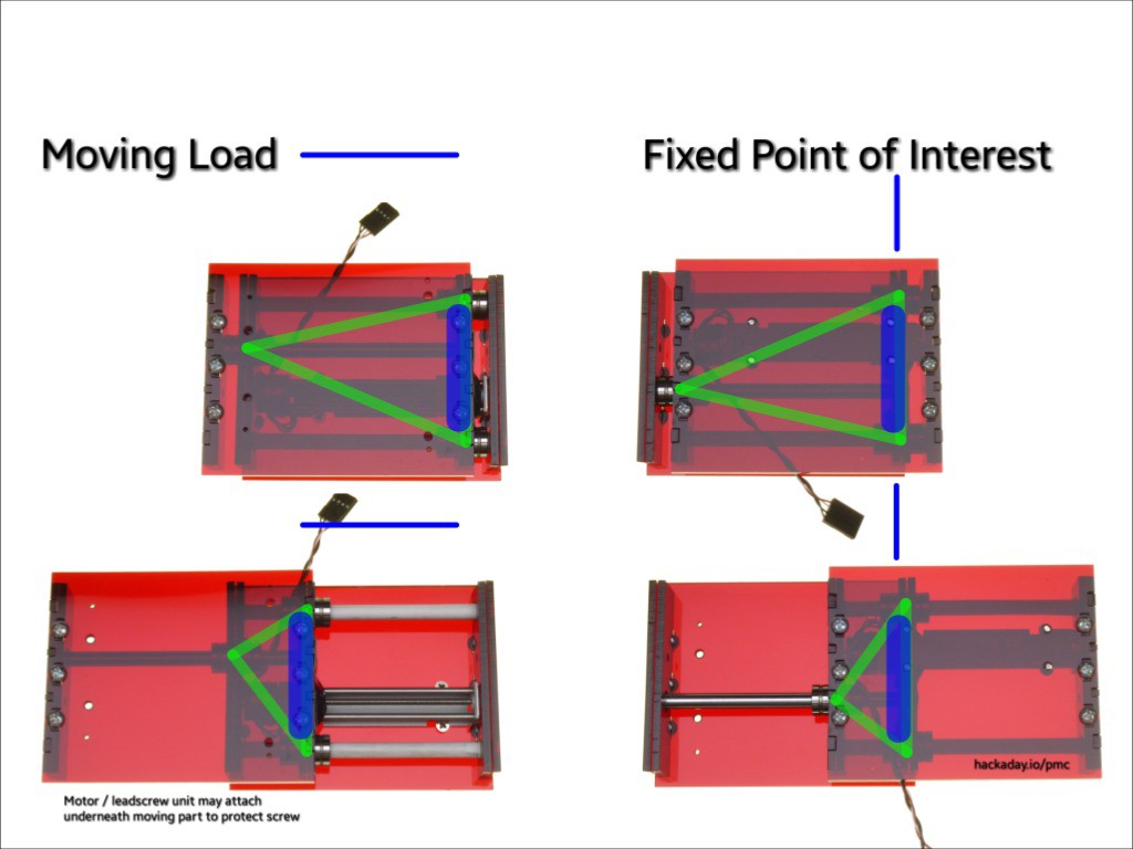
In the test linked above, this slider shifted half of a 30lb (14kg) moving load while oriented as illustrated on the left. Minamil uses the same orientation for the Z axis to carry the (relatively) massive rotary tool while the X & Y axes use the orientation on the right to move the workpiece around under the point where the tool acts on it.
The telescoping arrangement is obviously less stiff when extended. At full extension the "far end" gets pretty weak. Using the blue area minimizes the change in stiffness with extension. In practice with evolving versions of Minamil I have neither noticed any difference in capability as the axes extend, nor tried to flog it in the far corner of the work area. That's not much data except to say that it's working well enough that I haven't had to deal with the question. Within given constraints (size, money, etc.), machines generally have to trade off between range of motion and stiffness. More traditional carriage-on-track machines have past decisions about that baked in. I'll call it a feature that the telescoping arrangement makes that a run-time decision.
The telescoping design seemed like the best way to do something with parts in hand. If I've overcomplicated this build by not seeing the obvious, please comment. Apart from this specific instance, I think it's possible that the basic layout might have some legs as a way to pack greater range (with reduced stiffness) and stiffness (with reduced range) in the same box compared with conventional configuration under same constraints. For example, this layout can get equal range from shorter rods and slightly shorter rods deflect significantly less. But I haven't worked that through to discover why it's not already common. If you know, please comment.
The leadscrew can attach to either part, in case more abuse will happen to one side than the other. Minamil protects the leadscrews from milling debris.
Structure
Material
As one of the early ideas that gave this project a place to start, the design relies on 2D parts machine-cut from cheap -- i.e. thin and soft -- material. I first thought that would be 1/8in/3mm acrylic. Then I thought I'd use 1/8in hardboard for "rough drafts" and fit checking. Then the hardboard parts worked. So, hardboard. Just keep it dry.
In addition to cheapness of material, part of the cheap material idea was accessibility of capacity to cut it. As laser cutters become increasingly available in entirely ordinary places like schools and libraries, lasers able to cut 1/8in will be more common than lasers able to cut 1/4in+. I haven't heard of much community-accessible capacity to cut metal plate. Yet. (PS:1 being more exception than rule.)
So what to do with thin soft material? Minamil relies on 2D parts to hold a shape in the plane of the material by resisting skew distortion, but not so much for stiffness to resist bending or hardness to bear point loads.
Fastening
For lots of reasons, this has to be put together in such a way that it can come apart and go back together again. And again. And again.
The design idea that's made it this far uses tabs in slots to line things up and lots of #6-32 × 1/4in machine screws to hold them together. But no nuts or T-slots. The screws hold directly in the (thin & soft) cut parts. While that is definitely an "off-label" use of machine screws, I've been experimenting with this size/thread in 1/8in~3mm acrylic and hardboard with good enough results to keep trying different things.
In this case the tabs are split and screws driven edge-wise into the ends. With a tab fit into a slot, the slot keeps the halves of the tab together to hold a screw between them. This consumes less area in the part than nuts in T slots so parts can be smaller. In hardboard the screws form their own threads.
Getting the feel of driving machine screws into hardboard mush entails stripping a few threads. As a step toward reproducibility the cut parts include a couple of pieces for practice. Here they serve for illustration.

Novel? Please comment if you know of other examples of this sort of joint.
Alignment
Free and straight motion requires keeping the three rods parallel and the bearings concentric with the rods. Overconstraint doubles down on that while the vageries of cutting random bendy material with a realistically imperfect laser cutter conspire against.
Rather than just hoping for the best, initial ideas included assuming:
- parts will be cut from material of inexact thickness with only one finished side on a tipped bed by a skewed laser with an engraving lens in a machine that would cut a square as a parallelogram that is not a rhombus if it had concentric round drive pulleys
- distortions will be more consistent and independent than random or cross-coupled, at least across small groups of parts tiled together
In other words, betting on precision more than accuracy.
Very likely:
- cut edges will be far from square and by different angles on each side
- but not undercut -- the kerf will be narrowest at the bottom face and the top edge will be above or set back from the bottom edge of a face
- slot width <> tab thickness
- likely oversize to avoid undersizing
Having assumed the cut edges are probably not perpendicular to faces, but are never undercut:
- kerfs will be narrowest at the bottom
- the top edge of a cut face will be set back from or possibly directly above the bottom edge
- where the edge of a cut piece meets a perpendicular surface, it will always meet at the edge of the face that was on the bottom when cut
- the nominal outline of a cut part is valid only on the face that was down when cut
- cutting hardboard and other one-sided material with the good/finish side down will give the best available precision of shape from the material and laser cutter used
- for designing 2D parts for a 3D thing
- only one side of each part is useful for reproducing intended relationships between parts in contact
- thickness of the part and shape of the off side are certainly uncertain
- but we do get one fairly precise side to work with!
This design moderates the most deleterious deviations by focusing on the relative positions of the rods and bearings at the ends of the slider halves. At each end a single piece carries all the locating features for that end, fixing the relationships between them regardless of imprecise assembly. Cutting those four key parts for each axis with precisely the same inaccuracies should go along way toward achieving the parallel & concentric relationships among rods & bearings that will allow an axis to move freely through its full range of motion. The assembly needs to hold those parts close enough to mutually parallel at the same roll angle around the axis, but free motion should be less sensitive to imperfection in those relationships. When tiling parts for cutting, these four pieces for each axis are arranged and oriented to pick up similar inaccuracies with sufficient precision.[1] Or at least that's the idea.
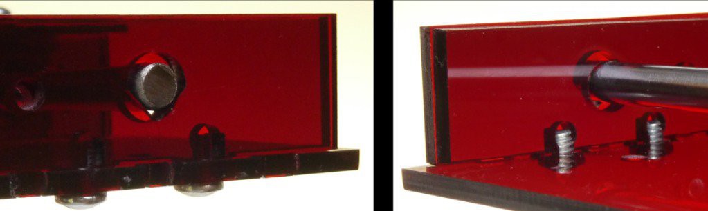
Conveniently, the rods and bearings are round. Where they intersect a perpendicular plane can be fixed by clamping them into a V block. If the V block is very short, small deviations from perpendicular have little effect, and less net effect over a bunch of V notches with equal spacing in parallel planes.
So the key features are a number of V-notched holes in single plates at each each end of each half of a linear slide for each axis. For each V plate there is a clamp plate with simple(ish) holes corresponding to the V notches. The clamp edge against the base plate has clearance so that the clamp can be pulled "through" a round thing lying in the V notch. The V plates have simple tabs to locate them by slots at each end of a simple plate that establishes the planar geometry of each slider half. These thin plates are loaded only at their ends so they function more by resisting skew and torsion than by resisting bending in simple curvature (which they do not). The clamps have split tabs for screws to draw them firmly into the base plate, which forces rods or bearings into the Vs and the V plate into the base. The roundish holes in the clamp plates have flat segments on "top" over the part to be clamped so that minor misalignment with the V plate doesn't force the clamped part harder into one soft edge of the V than into the other. Or at least that's the idea.
The transparent parts help to show this rod/V/clamp/base relationship:
[1] (a few paragraphs up) I expect to compromise this to make assembly easier to describe by keeping all V/clamp pairs face-to-face. I'm currently thinking that won't hurt the idea of getting precise alignment from inaccurate parts. The 1r0b V plate has only one V, so it really isn't a factor since the critical dimensions are relative between Vs. Of the three plates with multiple Vs, the 2r0b plate is symmetric, Flipping it doesn't change the distance between the rods. It might hold the two rods at slightly different heights and if the 2r1b V inherits a similar deviation then flipping 2r0b would ~double the effective deviation (roll around the axis) but that's a less sensitive dimension and the base plate probably has some twist anyhow. TODO: describe why started with V/clamp pairs face-to-face and epicycle around compromising that so Vs faced same direction.
Hardware
Manufactured components include:
- CH-SM1545 stepper motor & leadscrew assembly -- like more common generic 15mm stepper + 90mm M3 units but
- shorter - for a compact X-Y stack, the shortness matches well with the minimum width of this slider design to make a stack of two squares
- cheaper - still so but by a smaller margin now then when I started incubating this project
- LM6UU 6mm linear bearings
- smaller than 8mm parts which are the other cheap size
- cheaper than anything smaller
- 6mm x 100mm "linear motion" rod
- 100mm = 1x CH-SM1545 (88mm) + 4x 3mm material thickness
- a little $pendy to buy precut -- ~30% of cost
- hardened & chromed de rigueur for CNCish application
- but I don't know if this machine would ever wear into e.g. stainless rods
- available in longer pieces & common in printers etc. for scavenge
- but hard to cut with "common" hand tools
- but interested parties will have a Dremel(ish), and possibly sufficient patience
- overkill
- but 6mm bearings
- #6-32 × 1/4 screws
- an "off-label" use of machine screws, but I've been experimenting with this size/thread in 1/8in~3mm acrylic and hardboard with good enough results to keep trying different things, like:
- this design uses slotted tabs with screws driven edge-wise into the ends of tabs
- scavenge-friendly "PC case" size - but the complete mill uses a scavenge-hostile number of screws so probably a purchase item anyhow
- Paperclips - or similar wire to make springs
- 1/8 inch hardboard - finished one side
Leadscrew clearance/engagement
The animation and eight-view photo at the top of this page show the overall arrangement of base plates, V-and-clamp pairs, rods, bearings, and a motor/leadscrew unit to make up a slider assembly. The square top/bottom and side views show what looks like one of the V-and-clamp pairs and the leadscrew crossing through each other without showing what happens there.
Here's a closer look at the motor/leadscrew unit:

There is the leadscrew, of course, and a leadscrew nut buried in a plastic slider (the big tab gets clipped off the slider). Two rods parallel to the screw constrain the slider from rotating so that it moves along the axis of the unit when the screw rotates.
That unit gets attached by its frame to one half of the telescoping axis. The driven half of the axis has to engage with the screw somehow, without interference between the V-and-clamp combo and the screw or guide rods.
In the current design, the intersecting V and clamp are cut to clear the leadscrew & guide rods and also used to couple the driven half of the axis to the leadscrew. The clamp is cut to just clear the leadscrew and guide rods, while wrapping closely around the screw to lie flat against one side of the slider without cocking it on the screw. With that, the leadscrew nut can push the axis one way, but not pull it the other way.

After thinking about ways to attach to the leadscrew slider for two-way motion, I sidestepped the question by adding a second nut on the leadscrew to push in the opposite direction. For lack of a better idea, I'll call that an "opposer". To minimize backlash without jamming, the integral slider and added opposer should almost but not quite squeeze the clamp plate. Fine adjustment of that spacing provides backlash adjustment.
The "V" plate is cut more deeply to clear the opposer nut. That has the benefits of reducing the range of motion lost to extra stuff on the leadscrew, and avoiding uncertainty in the total thickness of two plates squeezed more or less together. The clamp is poorly braced to receive force applied this way, but the leadscrews do not generate much force. It helps that over dimensions of just a few thicknesses, the thin material appears relatively thicker and stiff enough to not be the weak link.
Like the integral slider, the opposer has to be constrained from rotating so that it moves in tandem with the slider when the screw turns. However, it can't be a simple copy of the slider because it has to be free to rotate for adjustment. Since it can't be constrained and free at the same time, it needs a hold/release mechanism of some sort. For initial trials I simply turned it into place and put tape over it, which can be seen with a close look at the photos of the red acrylic unit. That worked well enough to get by for a while but made assembly and adjustment tedious.
The better idea that has worked so far was to cut teeth around the opposer nut and bend a paperclip to spring into the teeth to lock it in place. For fine adjustment, the spring can be pushed away allowing the opposer to turn by fairly small increments. The small slot visible in the photo above near the leadscrew clearance allows the retaining spring to move radially while preventing rotation.

This arrangement has been working for backlash that I haven't measured any more precisely than <50 μm.

I don't know what other equipment this arrangement is like to describe it more succinctly. Comments? While both the integral slider and added opposer are part of the motor/screw assembly, the slider is constrained within the driving unit while the opposer is constrained by a lock/release spring on the driven half of the axis. The locking arrangement borrows from Sherline's backlash adjustment but the opposing nut is essential to coupling the driven part to the driving screw rather than a fine adjustment of an otherwise complete drive coupling.
A latent weakness of this arrangement is sensitivity to uneven wear on the leadsrew. I have no idea how long it will take for that to become a problem. That was a factor in thinking about alternatives to a simple M3 nut for the opposer. I first imagined finding brass M3 nuts. For that possibility I cut some pieces with hexagonal holes to fit a nut and teeth around the outside like the picture above for locking and adjustability. But I haven't found brass M3 hex nuts for reasonable cost. I tested with a steel nut briefly to check that the idea works, but I suspect that running a steel nut for long would wear the leadscrew. For early testing I simply cut and tapped little disks of the same material as all of the 2D parts. Like the hardboard structure parts have worked better than expected, M3 tapped hardboard nuts have also worked well so far. I still haven't found M3 hex nuts in anything but steel but I have picked up some brass ferules. I've bored out a toothed hardboard nut like the picture above and pressed in a brass ferule, but haven't tried it yet.
And they lived happily ever after.
Discussions
Become a Hackaday.io Member
Create an account to leave a comment. Already have an account? Log In.