 Paul McClay
(...and: are A4988s clocked?...)
aspirational statement: This project includes clear guidance for configuring hardware and software to drive these leetle steppers as hard as they'll go without cooking them.
current status: ooh... pretty pictures...
This lack of actual useful progress reflects ̶s̶o̶m̶e̶ much digression into scoping small differential signals riding large common mode steps with fast (20nsec) edges — in order to measure voltage across a low value resistor as proxy for current (i.e. "current shunt"). Because no current probe.
New skill unlocked: "gimmick". Because big fast common-mode edges.

Yes, I'm still fussing with A4988s
For the last several years and currently (early 2022), generic Pololu-style A4988 modules are the cheap current-limiting dir+step-signaled stepper driver, and this is about what can be done with those rather than what to get instead.
The generic modules I'm using are wired for full-time mixed decay mode (Rosc tied to GND). I've had them configured for 8x microstepping for most of the time that I've been using them because that seemed to work best in naive initial trials and I have not yet revisited the question.
Some of this may hold for some other somewhat similar drivers.
Atypical motors. Typical results?
¯\_(ツ)_/¯.
For this CNC project I'm using much smaller motors than pretty nearly any other CNC project ever:

I expect that load characteristics will affect driver behavior, and that this is an atypical load. Anyone who feels like checking any of this against a more commonly used sort of motor, please comment!
A naive idea: measure Δt by ΔR by ΔV for constant current
And thereby work out how much current won't cook the motor.
tl;dr: so far it looks like that may be a fair way to measure stator (coil) temperature but neglects eddy current heating internal to the rotor (magnet).
I tried something like this while playing with 15mm motors out of CD/DVD drives and made some progress by measuring coil R promptly after shutting off power. Resistance was already falling by the time my DMM stabilized on the falling value, so ? what it was while powered. I also tried measuring RC-filtered voltages across a coil or current shunt, which seemed plausible but uncertain considering I-don't-know-what pitfalls of RC vs RMS and floating a meter at ~30kHz. Shrug. I got my A4988-based drivers dialed to a current & μstep count that worked and left a lot of questions for later.
Some days ago I came back for another swing at questions left for later.
I'd like to come up with a recommendation for Minamil-like applications and to see what can be gained from "better" tuning of current, supply voltage, microsteps, acceleration, max speed, and possibly some heat sinking — and how to get there using simple/cheap/common instruments in line with the theme of this project. To sort this out, and validate any "simple" measuring scheme, I'd like a way to see some "ground truth" of what's really happening.
Oscilloscopes are great for watching voltage signals, but watching current is a different problem. One way to watch current is to pass it through a low-value resistor ("shunt") to create a small voltage drop proportional to the current and small enough to not significantly disrupt whatever you're measuring. That turns current into a simple "single-ended" voltage signal if one end of the shunt is tied to a stable reference, like ground, as are neither end of a full-bridge–driven motor coil. The "correct" solution is a current probe. But the probes used in the linked example cost $5k each and belong to the author's employer.
Measuring voltage across a shunt when both ends are moving requires measuring the difference between two similar signals. Most scopes can invert one of two channels and sum them to show the difference — when the difference isn't very much smaller than the range of smooth variations of the common signals. Isolating a small difference between violently thrashing PWM signals calls for a bona fide differential amplifier and, at least for me, some hours of thrashing to level up my scope fu.
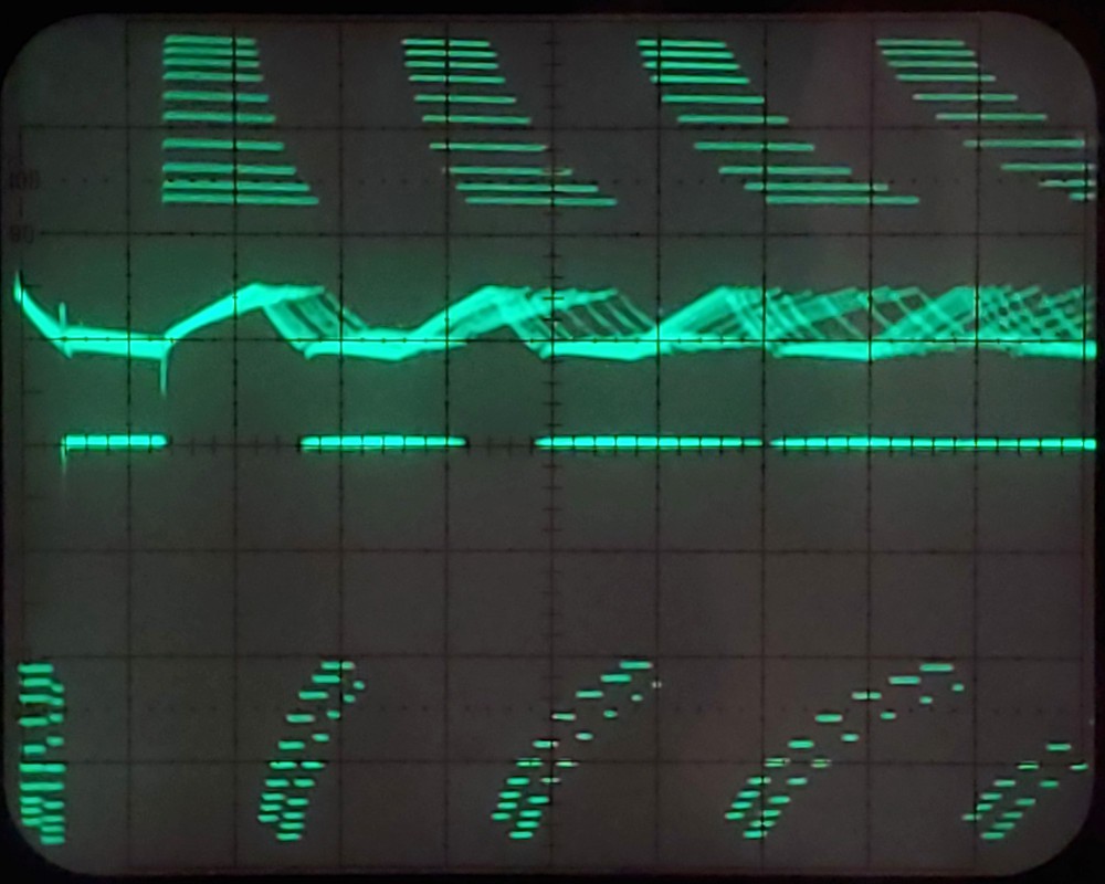
The animation below shows, for a single motor phase:
- voltage across the coil – the three-level stepped waveform
- current through the coil – the rising and falling angular waveform
- a potential proxy for net PWM "voltage" – the flat line moving with the current
- is difference between PWM levels at the two ends of the coil, each separately RC filtered to the controller/driver ground
- appears to track proportionally with the "average" of the current waveform, for some qualitative interpretation of "average".
Using the Dunning-Kruger corollary to Ohm's law, I figure the constant of proportionality is the resistance of the coil. And that change in this signal, while the A4988 is holding constant current, reflects change of coil resistance. Since the PWM runs some orders of magnitude faster than the thermal time constant of the coil, this can be filtered somewhere in between to work as a thermometer. And it's easy to generate and measure with a DC voltmeter.
(It seems to me that filtering each end of the coil separately relative to ground shouldn't be necessary. Hasty search results suggest that floating a cap between two resistors should work. My single attempt didn't go as expected. Left for later.)
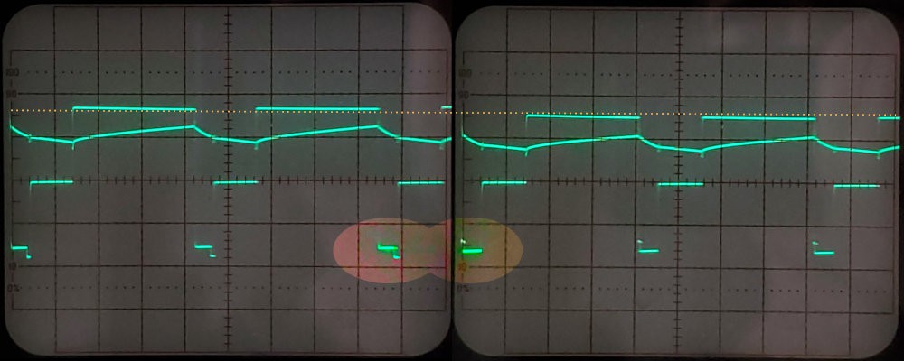
WIth the help of a very slow timebase (or pencil, clock, and adequate attention span), that turns into a graph of coil temperature rising with time:
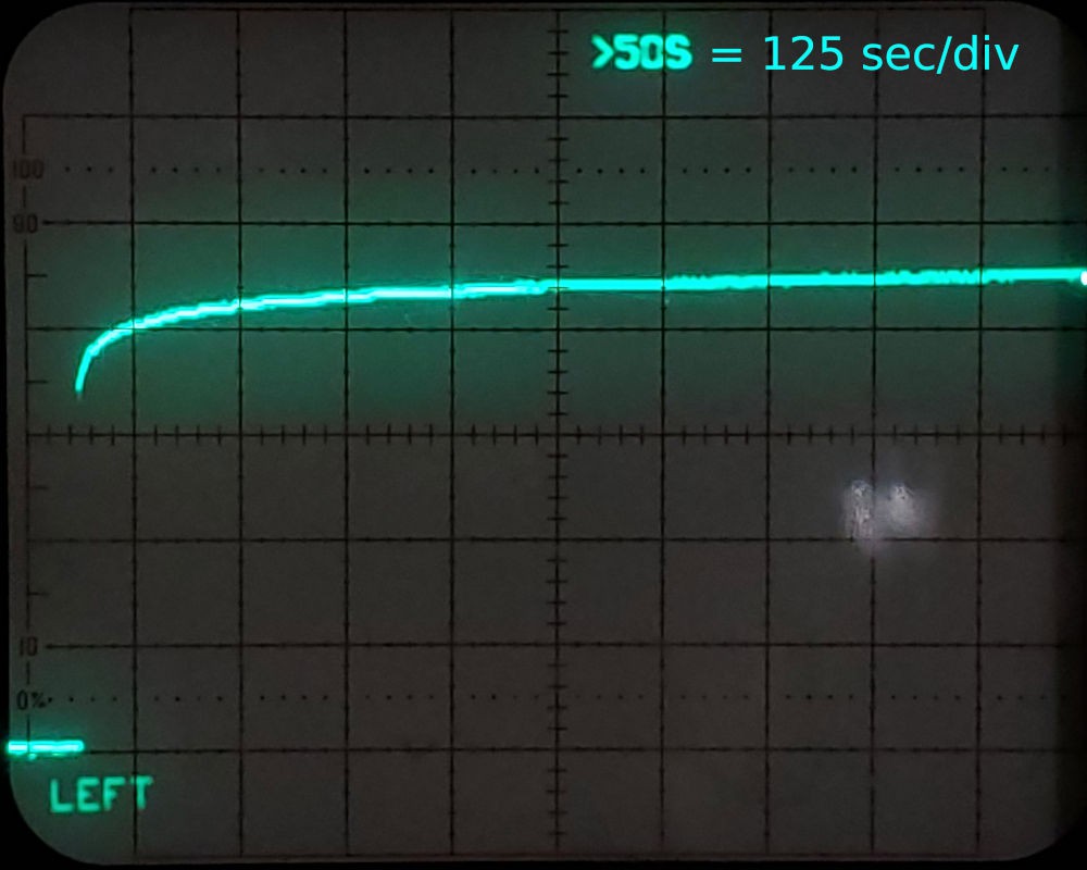
That shows temperature still creeping up after 15 min, and not really conclusively at equilibrium after ~20 min. (for the record: it did hold steady at the same level as shown in the last division).
And that's why it's easy for overheat to sneak up when you're not looking, and why it's hard (i.e. requires patience) to know how long is long enough to wait for valid steady-state conditions. And that's for an isolated motor not fastened to more thermal mass.
Numbers:
4.5div/3.4div = +32.4%
Temperature coefficient of resistance of copper; +0.393%/°C
%rise/tempco = +82°C
Starting temperature: 20°C (per nearby thermostat)
Estimated equilibrium coil temperature: 102°C
Alleged winding insulation class: E = 120°C
Conclusion: probably not burning the coil
Temperature. What does it mean?
Initially I "knew" the limit to motor operating temperature would be the Curie temperature of the magnets. Then I read that magnets begin to degrade at lower temperatures — some sources saying 80°C and all sources saying it very much depends on the magnet so check the manufacturer's specs. The motors I'm using don't come with any such spec. (and I don't believe what they say about current and voltage — at least not for continuous duty).
It seems to me there must be a fairly common lowest-cost magnet composition for cheap steppers, with known temperature limits, but I haven't found any such thing. Please comment if you know something about that.
When looking for info more specifically about operating temperature limits for steppers, I've been finding a) lots of non-specific commentary about magnet temperature, and b) a few manufactures answering the question by citing winding insulation class rather than anything about magnets. [...maybe they're answering the question of when their product will start a fire they might have to pay for vs. when it will turn into a pumpkin...?]
Specs for the motors I'm using in this project allege insulation class E, which is nothing special at 120°C. So maybe that (minus some allowance for non-uniform temperature) is the limit?
And I had speculated that the phase windings maybe would be the source of heat and therefore the hottest part of the motor and upper bound to magnet temperature. Or at least nearly so. Maybe.
But I don't know. So I wanted a baseline check of motor function, like vertical lift capacity at some speed, to validate health or detect diminished capability. Measured vertical lift at 3000 mm/min, for initial voltage, current, accel, etc.: >350g.
I wasn't fretting temperature, because the motor case felt much less hot than earlier tests of holding one winding at max current for long times — as expected from experience that motors heat up much more when holding position than when moving.
Then I tried some slower lifts, and lifted well over 500g at 500 mm/sec. After working up to a load that the motor couldn't lift, the motor was no longer able to lift similar loads at all. It's capacity was reduced by, roughly, about half.
Temperature? The motor case was nowhere near as hot as when holding position for earlier winding temperature tests. Apparently I'd discovered another way to heat the magnet.
And, yeah, on further reading I find that varying stator fields create eddy currents in the rotor that heat the rotor internally, with PWM chopping harmonics cited as a factor. So maybe pulling heavier loads increased the current ripple (ironically decreasing the average current, if so) which increased internal heating of the rotor. ?.
If so, that could be a reason to minimize motor supply voltage where more torque is worth less speed. And/or to fear slow moves with maximum load.
But then this source suggests that heating due to current ripple (above fundamental drive frequency) heating doesn't amount to much until the ripple gets bigger, or a lot bigger, than the current. These trials have been nowhere that.

In my interpretation of the linked source, that much PWM ripple would add insignificantly to rotor heating. The fundamental is not quite sinusoidal, apparently approaching what that supply voltage could support, which would add some low harmonics, but that doesn't look awful. It does look like a reason to try removing the 0Ω "resistor" that forces constant mixed decay. This was a load & speed that apparently did not hurt the motor.

I don't think I captured a trace from a successful slow/heavy lift. I think this was stalled. Anyhow, the PWM ripple doesn't look any worse here, although the more angular shape of the cycle will have some more low harmonic content. The symmetric straight slopes and pointy corner at the bottom vs rounder top are puzzles.
Anyhow... that all makes estimating magnet temperature harder than the naive idea that I started with, by a margin large enough to matter.
As ever, finding answers starts with asking relevant questions. It turns out there's quite a lot written about estimating rotor temperature of permanent magnet motors. This example says flux linkage is the way. Because magnets have tempco too. Not sure if that's going to fit with the "simple/cheap/common instruments" theme tho.
And I still don't know what is a "safe" temperature.
Random
Things found along the way.
Not really news, but delivered current changes significantly with motor supply voltage [sometimes]. That's not entirely harmless. It's a known thing, and I might have worked it out if asked directly, but I wasn't really mindful. It seems like it would be worth saying more directly in docs/references/tutorials/etc.
[deletia]
Aaargh. This section about current & supply voltage was short and I was done-ϵ with this overwrought log of no progress. Oh, but just one last little detail... that might possibly have made a difference further down the page... it will just take a moment...
Or not.
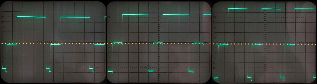
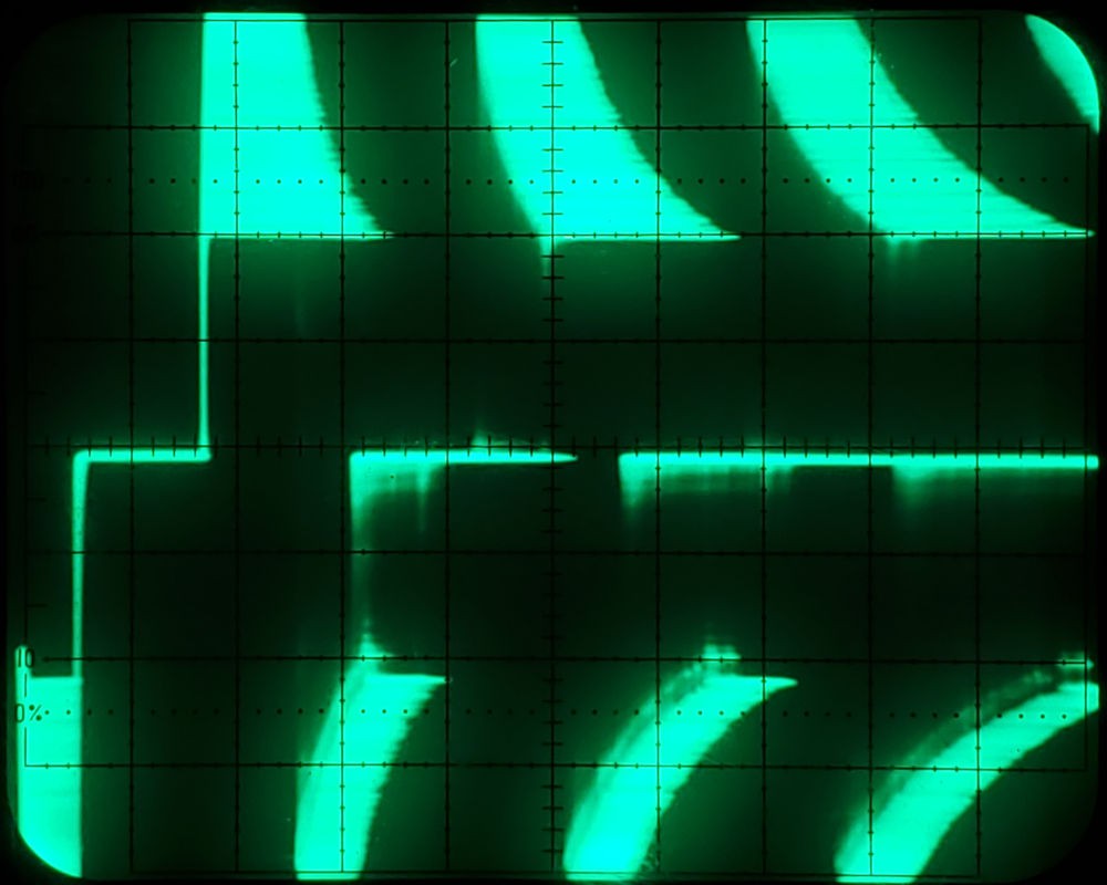
The three scope views below are each a composite of three-trace displays like the animation above — coil voltage, coil current, and a DC representation of time-average coil PWM voltage scaled to the "middle" of the current waveform — for a range of supply voltages. These views are shifted down so that the short segments across the bottom are PWM at "ground" for slow decay, the longer segments above are the driving pulses, and the negative fast decay pulses are not shown.

- Left – very low motor V: [this part might be a red herring, see below — or it might not be, see further below] Current varies almost directly with supply V, because reducing V below a minimum apparently depresses the current sense trip point. That smells like a reason why the A4988 specifies a minimum motor supply. However, the minimum motor V for stable current sense reference appeared to be about 10V rather than the datasheet value 8V. Hedge: I didn't carefully re-double-check that at the time and for this part I shot a bunch of pictures before tearing down that setup to make room for visiting family (priorities, eh?).
- ... And as I type I'm remembering that I'm regulating the logic supply down from the motor supply so regulator drop-out might matter here, but ~5V should be plenty of headroom... Oh, but there's another regulator drop in that chain... ...Ok, so I just put a meter across that: 3.6V min drop across the two (1.7+1.9) and the max "5V" level is 4.9V when supplied with >8.5V. I thought the top of "very low" was ~10V. It looks like the current sense threshold drops at supply less than 1.5V down from 10V, but too close to call without another look. Scope traces are scaled for pretty pictures, so not showing voltage. So now I think it looks like I was depressing the 5V logic supply — but see further below. Bah.
- Center – not very low motor V: current waveform and PWM average hold very close to constant while the waveform compresses in time with shorter driving pulses.
- Right – higher motor V: current ripple deepens & PWM average drops with increasing supply V.
Maybe the left/low end was my goof. And maybe the difference between center and right is just small variation having small effect vs larger range variation having larger effect... But look at the PWM "ground"/slow decay levels vs. the contrasting dotted reference line:
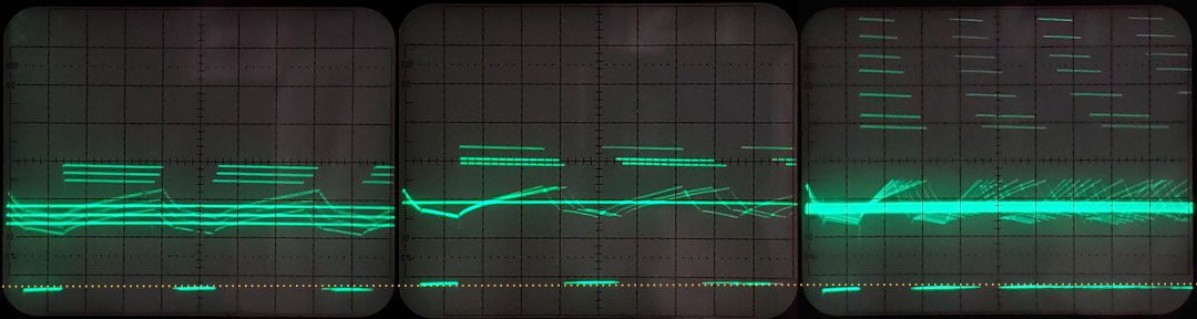
Those are step changes between two distinct levels, suggesting there's something actually different about the "Goldilocks" zone.
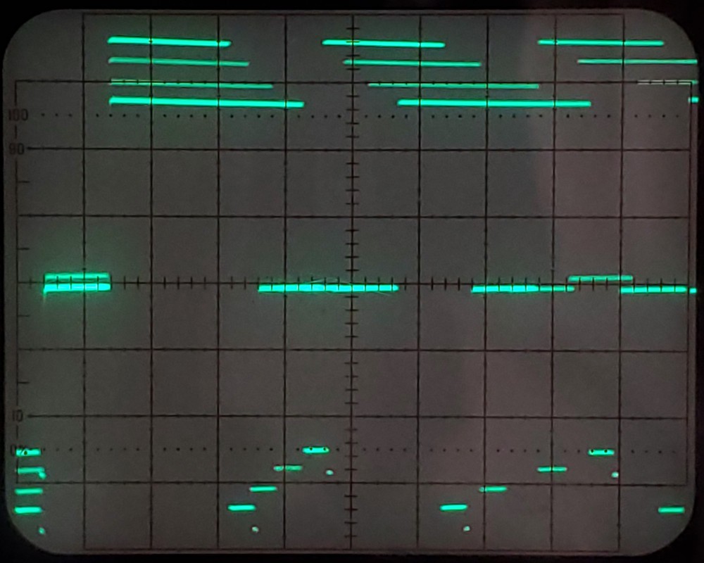
Shifting the PWM signal back to center beings the fast decay pulse back into view.
In the middle case where the slow decay segment is higher (smaller negative offset from reference "ground"), the fast decay pulse is flat. In the other two cases where the slow decay segment is lower (less small negative offset), the fast decay pulse shows a step near the end of the pulse. Dunno what that indicates other than distinguishing three distinct conditions.
This shows a range of traces through the middle zone between the highest lower voltage and lowest higher voltage where the fast decay step occurs. Slow decay segments appear at just two levels. The slow decay level change with supply voltage does not coincide exactly with the appearance/disappearance of stepped fast decay, and passes through a region of seemingly random alternation between the two levels, manifesting here as a missing high-level slow decay segment in the middle. That last bit probably needs a rewrite.
detail:
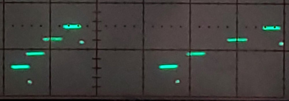
In the very low voltage range: once the step has started on the right/at the end of the of fast decay period, the step slides to the left/beginning of the period as voltage decreases further.
In the high voltage range the step again shifts from right/later to left/earlier with increasing voltage, but does not shift as far as for very low voltages. For supply up to a little over 20V (limited by diff. amp input limits, fixed pre-amp attenuation, and laziness to change the pre-amp attenuation).
The "very low voltage" case might be a red herring due to unwittingly depressing the logic supply voltage, which is also the top of the Vref voltage divider. But I don't know how that would cause the step in fast decay level and/or shift in slow decay level. Those things look more like a real difference in what the driver is doing. The appearance of similar fast/slow decay step/shift at higher voltages suggests that it's not just a marginal undervolt behavior. To me at the moment, the symmetry looks like an effect that reflects getting further away from a happy middle. But ¯\_(ツ)_/¯.
Aaargh. So much digression. Attempting to digress less, I tied to ignore this part. See how the animation at the top of this log shows the fast decay step in high current frames without comment? But I did not succeed.
And I didn't even get back to the motivating question: does the apparently proportional relationship between PWM average voltage and current hold for varying supply voltage? Because when increasing resistance calls for increasing PWM drive, that's somewhat like reducing supply voltage, and if that affects PWM/current proportionality then it would skew the PWM/resistance/temperature idea.
Moving on...
Bad resonance around 1000 rpm:
 It sounds bad too.
Just a pretty picture: No surprise that constant off time -- including fast & slow decay periods -- remains constant and the on time in/decreases with de/increasing supply voltage.
The horizontal widths of the dark off-time bands on the top vary with supply because jitter expanding the lit on-time bands varies; the clear off-time trace on the left before the first on-time shows actual uniformity of off-time.
More digression: Do A4988s run on clocks?
Here are switching transients in the differential signal following one end of a coil -- which should be no signal. The down-pointy spikes mark the ends of the fixed off periods/starts of on periods. The up-pointy spikes mark the ends of on periods/starts of off periods -- when the sense voltage matches the threshold voltage. Fast/slow decay switching happens at the other end the coil and doesn't appear here. The driver is holding constant(ish) current. The trace starts from on->off events.

In this steady state the on periods are all nearly but not exaclty the same duration. The fist down spike is clear because those events trigger the trace. The following up spike is a little fuzzy because those events (Vsense>Vthreshold) happen after almost but not exactly the same delay. The second down spike is similarly fuzzy because those events happen at some "constant" time after the up spikes. However, the down spikes show a hint of structure. On looking more closely, the horizontal spread of the up spikes (on times) looks like more-or-less Gaussian blur. The down spikes have similar horizontal spread, but clearly quantized in time after the trigger event.
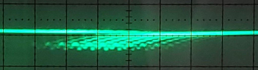
The A4988 datasheet says:
The internal PWM current control circuitry uses a one-shot circuit to control the duration of time that the DMOS FETs remain off.
I roll to disbelieve. Is the "one-shot circuit" not a one-shot circuit but instead a digital timer that gets started at a time quantum after something on a clock recognizes that the current sense comparator has tripped off the on phase (which apparently happens asynchronously)?
The expanded trace above shows 0.5 μsec/division. Do A4988 drivers run on a ~5MHz clock? That plausibly could be the "oscillator" that "Rosc" influences to adjust off time -- by adjusting the clock speed.
Was this obvious to everyone else and I was the only numbskull who assumed A4988 logic worked asynchronously from control inputs, Vsense, and "one-shot" timers?
Discussions
Become a Hackaday.io Member
Create an account to leave a comment. Already have an account? Log In.
"Was this obvious to everyone else and I was the only numbskull who assumed A4988 logic worked asynchronously from control inputs, Vsense, and 'one-shot' timers?" I have absolutely no evidence of this, but I feel like there's a non-zero chance the cheap A4988 boards use counterfeit ICs that might have subtle differences like that.
Are you sure? yes | no
Certainly could be counterfeit. But such a difference would be internally not subtle at all. If a counterfeiter went to the trouble to designing a new thing, why not make it a bona fide legit new product? (rhetorical question)
Are you sure? yes | no
This CH-SM1545 AliExpress listing specifies an operating temperature range of 0-55°C, but your comment on the manufacturer's ratings still stand: https://www.aliexpress.com/item/4000145635198.html
Are you sure? yes | no
I took the 0-55°C range to indicate acceptable ambient temperature. Considering that I don't believe their voltage/current claims at room temperature, specifying any greater ambient temp seems pretty arbitrary anyhow. Could make sense if they also specified a maximum on-time and {duty cycle or minimum off-time}.
In any case, I hope you gained some benefit for your time spent reading my inconclusive ramble!
Are you sure? yes | no
Yeah, I thought that could be possible, but 55°C seemed just toasty enough for me to be unsure. I probably should've clarified that.
Are you sure? yes | no
Hmmmm, this datasheet for a stepper chosen entirely at random on Digi-Key specifies an "Ambient temperature" of -20...+50°C and a "Temp rise" of max 80°C: https://www.trinamic.com/fileadmin/assets/Products/Motors_Documents/QSH2818_manual_Rev1.05.pdf
I'd *guess* Temp rise is the figure you're looking for, so around 80°C seems like a good ballpark guess?
EDIT: Wait, I misremembered what the log said, I think you already saw this or something similar...
Are you sure? yes | no