Close
0%
0%

Isolated USB null modem

Connect two hosts via a serial connection, but with total galvanic isolation

Similar projects worth following
I needed a way to connect two USB hosts via CDC devices. You could do so by just buying a pair of USB-RS232 dongles and connecting them with a null modem, but that still winds up connecting the two hosts' grounds together. If their grounds are not equipotential, the result could be disastrous.

As you look at the schematic, note that there are two 5 volt rails and two grounds. Nothing is allowed to cross over the isolation barrier at all (except light inside the isolators). We need to move 3 signals in each direction. The SI8035 is a logic level isolator triplet, so we need 2 of them for 6 signals (3 in each direction). Take careful note that one of the isolator chips is upside down relative to the other one. That's because each host needs one primary and one secondary side.

The inputs and outputs of the isolators are just simple logic level I/O that's compatible with the I/O lines on the UART chip. The tricky part is in understanding that the secondary side shares the 5 volt and ground of the host it talks to, but the matching primary side shares its 5 volt and ground with the other host.

The wiring of the null modem is TXD->RXD, CTS->RTS and DTR->DSR+DCD, which is a fairly standard configuration.

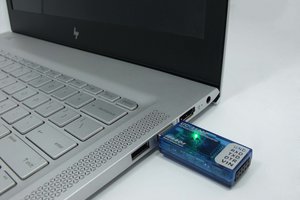
The USB UART chips are the Cypress CY7C65213. They present a standard CDC interface over USB. The USB connectors are USB C 2.0 types. They can connect to USB C hosts or to legacy hosts via an A->C cable.

The last note is that you should take careful note of the fact that the groundplane for each host stops just beyond the line of isolator pins. Under the isolators there is no copper at all. The SI8035 has an isolation voltage spec of 1 kV and the two ground planes are 6.3 mm or so apart, which gives you up to 2 kV, depending on what pollution degree you choose. so the lower of the two - 1 kV is the isolation spec for the project as a whole. Still, for the ordinary use case, this should be plenty. Two hosts close enough together to reach via USB that have a ground potential difference more than a handful of volts would already be a fairly dangerous situation.

Adobe Portable Document Format - 54.48 kB - 09/13/2020 at 05:20

Preview
Download

sch - 176.85 kB - 09/13/2020 at 05:19

Download

brd - 65.47 kB - 09/13/2020 at 05:19

Download

Standard Tesselated Geometry - 7.70 kB - 09/16/2020 at 17:17

Download

Standard Tesselated Geometry - 1.45 kB - 09/16/2020 at 17:16

Download

  • An alternative to optical isolation

    Nick Sayer08/27/2020 at 01:06 0 comments

    The project works as it's currently designed, but I was turned on to a different sort of isolation solution by a Twitter follower (I'm sorry, but I don't remember who as I type  this). It's the SI8035AA-B-IU, which is a 3 channel logic level isolator. I believe internally the isolation barrier is crossed with RF transmission (which you could argue is induction) across an insulating barrier. The isolation drops form 5 kV to 1 kV, but that's still plenty for this application. The big difference is the cost. One of the SI chips is about $1.20 or so, and two of the optical chips (because each has 2 channels instead of 3) are just shy of $4. And, of course, you have to double those prices for each unit because there's a need for the same number of channels in each direction.

View project log

Enjoy this project?

Share

Discussions

MagicWolfi wrote 08/25/2020 at 19:22 point

The USB bridge has a max data rate of 3Mbps and the opto isolator is max 20Mbps. What was the max data rate you could achieve during testing?

  Are you sure? yes | no

Nick Sayer wrote 08/25/2020 at 19:25 point

I haven't tested beyond standard serial baud rates, like 115.2 kbps. But the CY7C65213 says it can do up to 3 Mbaud and I don't see any reason this device can't live up to that.

  Are you sure? yes | no

drenehtsral wrote 08/25/2020 at 17:45 point

One thing that might be interesting to consider would be using so-called "digital isolators" (marketing name) instead of optical isolators to increase the maximum bit rate. They generally use capacitive or inductive isolation and are available with >= 2kV isolation.

Either way this looks *way* handy!

  Are you sure? yes | no

Nick Sayer wrote 08/25/2020 at 18:00 point

I'm going to try one (actually two) of those. It doesn't quite get as high in isolation voltage, but it's certainly good enough for this application, and it's cheaper.

  Are you sure? yes | no

Similar Projects

Does this project spark your interest?

Become a member to follow this project and never miss any updates