 kevarek
--- USER INTERFACE ---
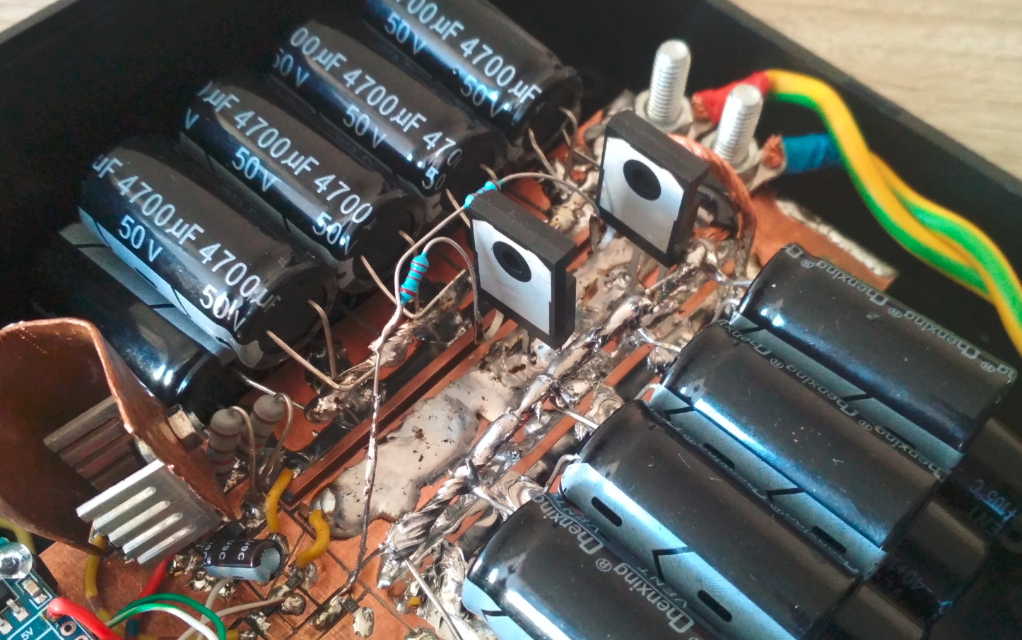
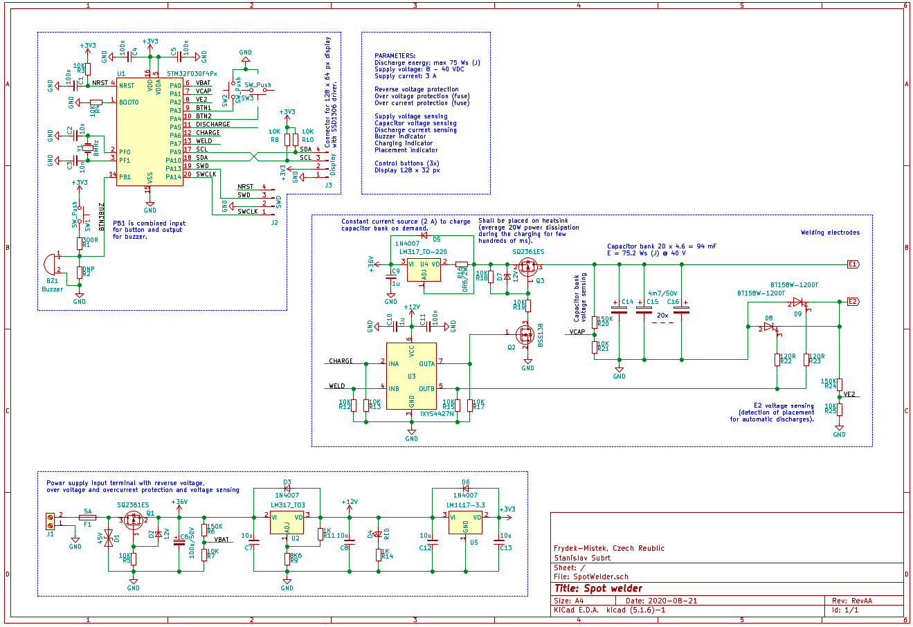
Core of this device is 20 x 4.6 mF = 94 mF capacitor bank with maximum voltage rated at 40 V which equals to 75.2 J of energy. Capacitor bank is charged via 2 A current source realized with U4 (LM317) - make sure to be able to heatsink 5 W average power dissipation. Charging is enabled with CHARGE signal from MCU switching on the Q3 PMOS transistor. Voltage is sensed on VCAP voltage divider and when voltage required for specified discharge energy is reached the charging is stopped.
--- ELECTRODE PLACEMENT SENSING ---
Capacitor bank voltage is always maintained at fixed voltage approx 2V. When the voltage is lower, transistor Q3 is turned on and capacitor is charged to desired voltage. Voltage on electrode E2 is sensed using voltage divider formed by R24 and R25. When electrodes are not connected, sensed voltage is 0V, but when both electrodes are attached to welded specimen, voltage rises to 2V (capacitor voltage) and thus electrode placement is detected.
--- WELDING PROCESS ---
There is a 1s delay between electrode placement detection and welding process start in order for operator to have some time to adjust electrode position and pressure. If electrodes are still connected after this delay capacitor bank is charged to desired energy (=voltage) and when it is reached both thyristors D8 and D9 are triggered and capacitor energy is discharged.
After fixed delay (100ms) voltage of the capacitor is sensed and if it is more than 3V discharge is marked as fail.
--- POWER STAGE ---
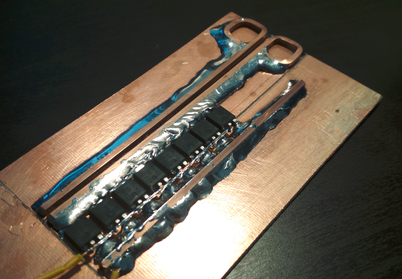
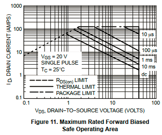
Initially I wanted to use few power N-MOSFETS (NTD5804N, 7.5mOhm; 70A nom; 125A@10us) in parallel to switch the welding current but I burned down 10 in parallel and later 20 in parallel. It was very stupid idea and I should have simulated it first :)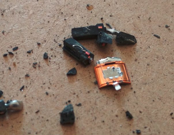
Supply voltage is displayed on display together with set discharge energy, energy currently stored in capacitors and maximum possible discharge energy with given supply voltage.
Discharge energy is set with 5J steps using green (increment) and yellow (decrement) buttons.
All the interactions, results, failures etc are also announced by beeper sounds.
Welding is started with attaching electrodes.
--- PARAMETERS AND FEATURES ---
Discharge energy: max 75 J (Ws)
Supply voltage: 8 - 40 VDC
Supply current: 3 A
Reverse voltage protection
Overvoltage protection (fuse)
Overcurrent protection (fuse)
Supply voltage sensing
Capacitor voltage sensing
Buzzer indicator
Display 128 x 32 px
Control buttons
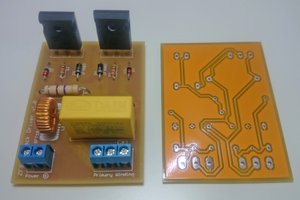
--- TESTING ---
(sorry for low quality)
0%
0%
Capacitive discharge spot welder
Small spot welder with maximum discharge energy 75 Ws (J).
Become a Hackaday.io member
Already have an account? Log in.
Just one more thing
To make the experience fit your profile, pick a username and tell us what interests you.
Pick an awesome username
hackaday.io/
Your profile's URL: hackaday.io/username. Max 25 alphanumeric characters.
Pick a few interests
Projects that share your interests
People that share your interests


 Azri Jamil
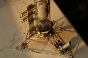
 DeepSOIC
 mircemk
 MagicWolfi
I would like to know, how it is possible that thyristors turn of after pulse?
Typical thyristors stay turned on and you can't turned them off using gate.