kevarek
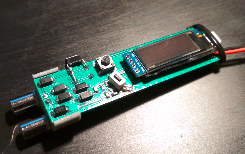
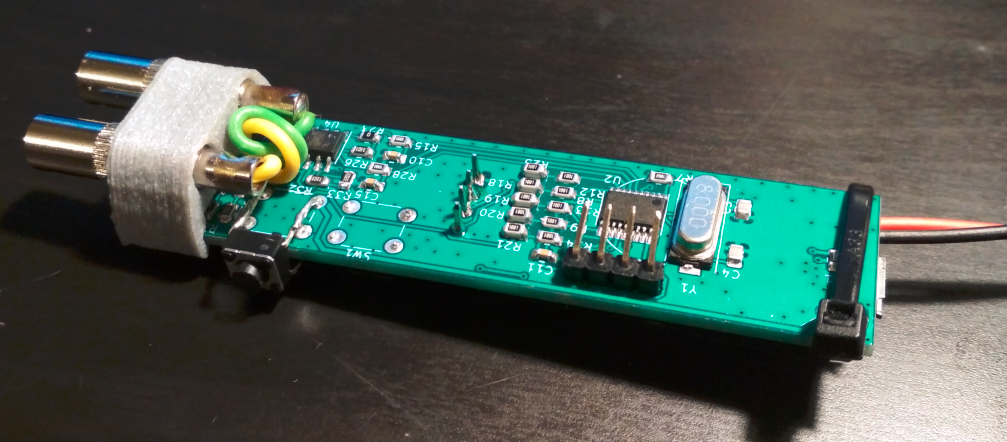
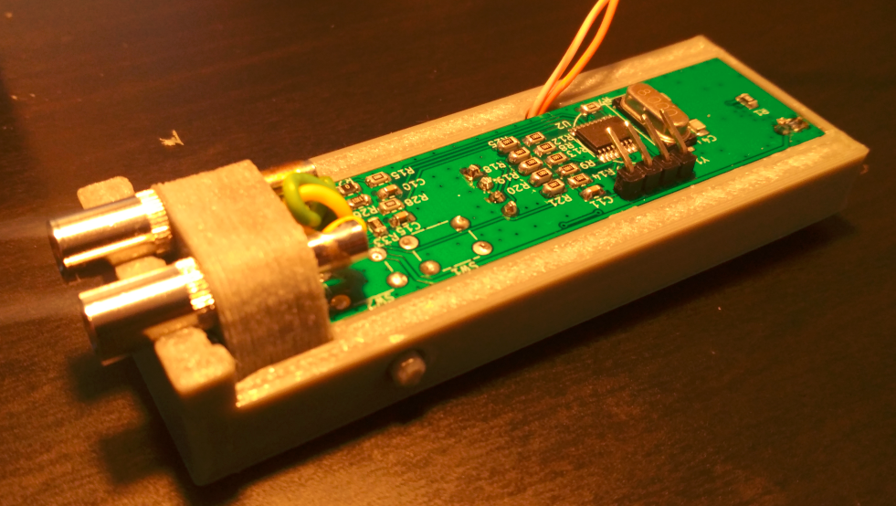
Smallest/cheapest MCU from STM32 family has been selected to control the measurement process. Device under test (DUT) is connected between test 1 and test 2 terminals. Diodes D3 to D8 are protecting terminals against connecting to charged capacitors.
In order to generate test signal sinewave the R2R ladder has been used to emulate 5-bit DAC (PA3-PA7). Check nice article here on hackaday: https://hackaday.com/2015/11/05/logic-noise-digital-to-analog-with-an-r-2r-dac/. This signal is divided, buffered, filtered and shifted by U5A opamp in inverting configuration. Final test voltage is maximum +-0.25 V and maximum test current is limited by R34 resistor to 5 mA. Such a low test voltage allows to perform some basic measurements of components in circuit without desoldering.
Current through the DUT is measured in both directions using U5B opamp in transimpedance configuration. Advantage of this circuit is that it keeps its inverting input at the same voltage as its non-inverting input (which is held at half of reference voltage) - this means that while current is within measurement range (ensured by R34) the voltage on test terminal 1 is exactly the same as half of ADC reference voltage as well. And due to this the measurement of voltage across the DUT could be very nicely measured in both polarities using only positive power supply rail. Two voltage sensing ranges are used (U4B for 10 Ohm range and U4A for 100 Ohm range of measured impedance). I recommend reading similar device build log here on HAD: https://hackaday.com/2019/07/20/create-a-low-cost-high-accuracy-lcr-meter-with-an-stm32-mcu/.
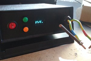
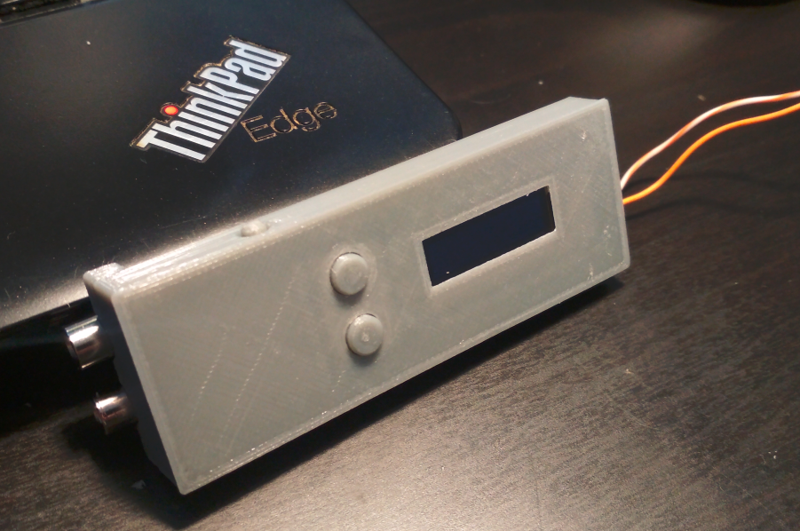
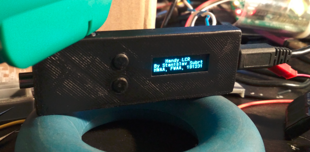
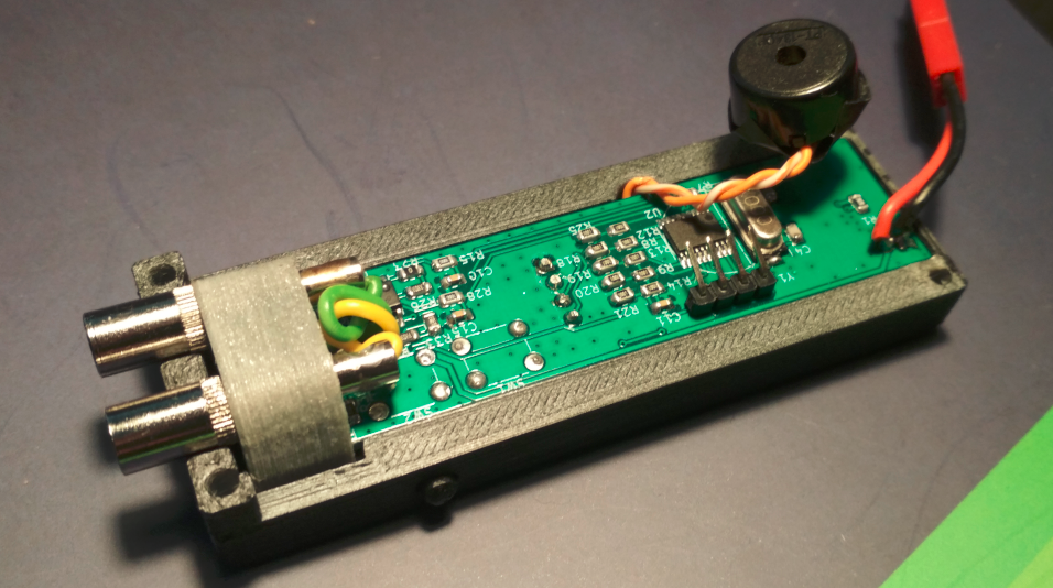
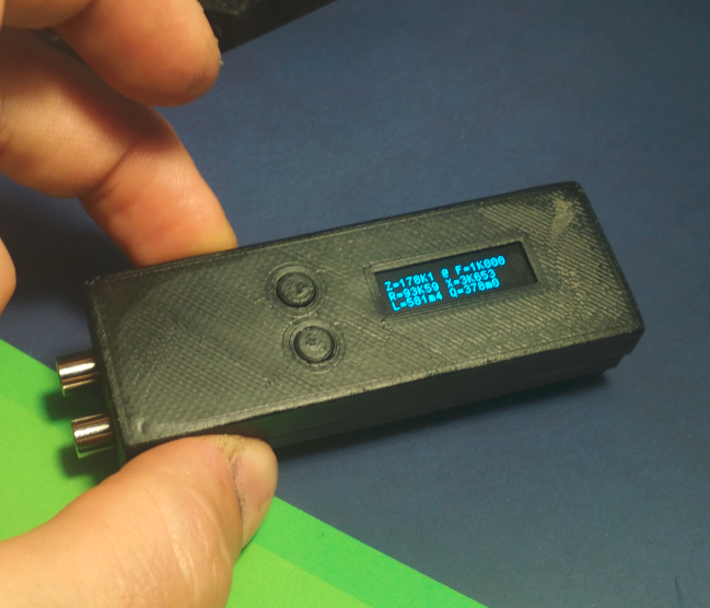
To plot measured data small 0.9” OLED SSD1306 display with 128x32 px resolution is connected to MCU via I2C interface. Due to lack of available pins on MCU single pin PB1 is used for battery voltage sensing, driving the piezo beeper and also reading state of 2 buttons (second button is not present in schematic but it is just connecting PB1 pin to ground via 2K resistor). The trick is that when any button is pressed (or both) the voltage is distinguishable from battery voltage sensing. See the simulation in LTSpice available from attached HW repository or 7z package.
To power the device Li-Po battery with voltage 3.7 V has been chosen. Voltage is regulated to 3.3 V with low dropout regulator. Charging chip U1 is powered via micro USB connector with reverse polarity protection transistor Q1 (too paranoid) and some basic pulse and ESD protection D1. Regulator and MCU is only powered when main button SW2 is pressed which ensures low power consumption when the device is not in use.
To evaluate impedance of DUT synchronous detection technique (also known as lock-in measurement) is used to extract complex voltage and complex current on/via terminals. This technique also subtracts any offsets caused by the circuitry. For more see: https://www.zhinst.com/americas/resources/principles-of-lock-in-detection. Impedance is calculated as complex division of voltage and current (see Agilent or Hioki impedance measurement handbooks: https://www.hioki.cn/ckeditor_assets/attachments/812/.pdf). Now there is another very cool trick - there is no voltage reference for precise measurement in the schematic, but since the measurement error is the same for voltage and current measurements it is eliminated by the division in the impedance calculation.
Many floating point operations are needed which ended up with exceeded FLASH memory very soon. Memory footprint has been greatly reduced and the whole program could finally fit into MCU by replacing provided GCC software floating point operations by QFP library https://www.quinapalus.com/qfplib.html.
USER CONTROL:
- main switch on/off button shall be pressed in to keep the device active
- upper button selects measurement frequency (short press lowers the frequency, long press increases the measurement frequency).
- lower button short press starts short measurement and long...
Read more »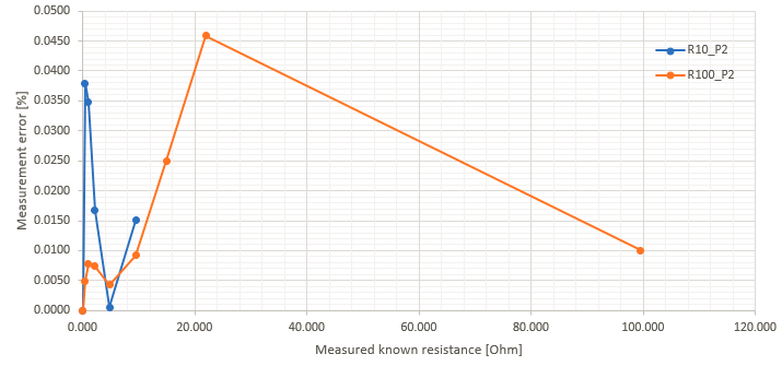
 Dr.Stone
 Andy
Andy
 Marek
Marek