 Dominik Meffert
In this project I want to try melting metal powder with an arc in an inert gas chamber to create 3D objects. Inspired by HomoFasciens video https://youtu.be/Y-yjsyJQGfI. in which he burned holes into a piece of paper to print with an hacked arc lighter, I started this project.
First I connected an arc lighter module to a 3D printer and printed on steel powder which changed its color and bond toghether a bit.
After a short time the arc lighter module stopped working, so that I thought about building a more capable power source.
So I spent some time of research, to learn how to build a HF starter to start the arc without touching the powder and built one.
I tried different voltages, currents, AC and DC and figured out, that it worked the best with rectified mains voltage which is for safety isolated from ground via a 1:1.09 transformer and gives 340V DC. I added 4x 100ohm 100W power resistors to limit the current to 0.85A, what seems to be enough for melting the powder.
With 340V DC the arc ignited every time and kept on going on the last try until I shut it off. I tested it on a distance >1mm.
I tried to test the welding system on the printer, but it creates so much emi/rfi noise that the printer controller keeps rebooting as long as it is active.
So I'm currently working on a way to shield the printer controller from noise. For doing so I'm planning to send the trigger signal for the arc via an optical toslink cable, I'm also planning to use shielded cables for the stepper motors, place the controller in a grounded metall box and use Trinamic's StallGuard feature for homing without limit switches. Hopefully that will make printing with an HF start welder possible.
I'm currently working on a test stand for printer designs, which will contain the welding system and printer controller.
It will be a bit like a shelf on which the printer (mechanics + motors) will be placed.
The printer will later be covered with a transparent enclosure which will then purged with shielding gas.
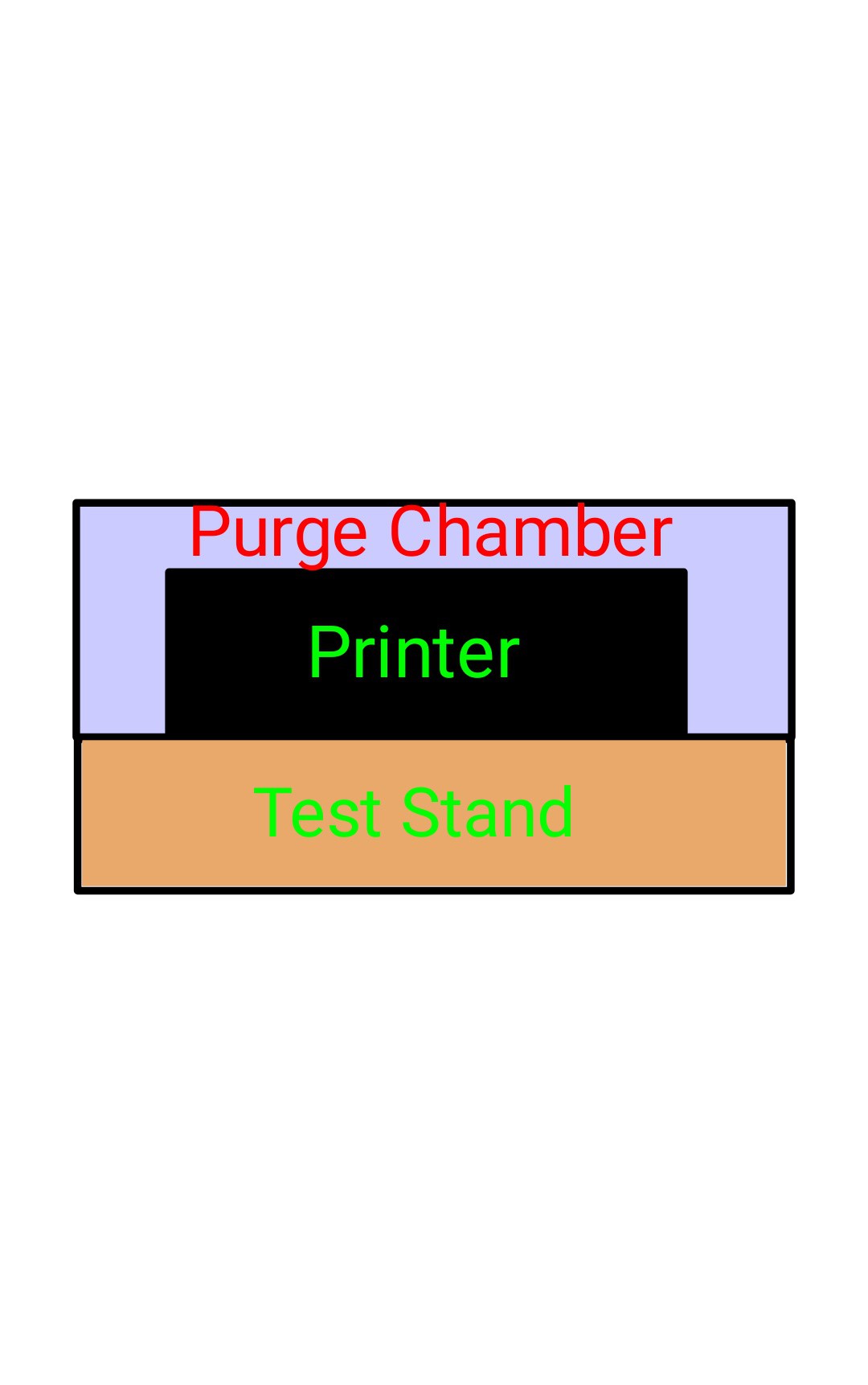
Maybe the dimensions of 1000*600mm are a bit too large, but I don't know the dimensions of the later printer so I built the test stand a bit larger.
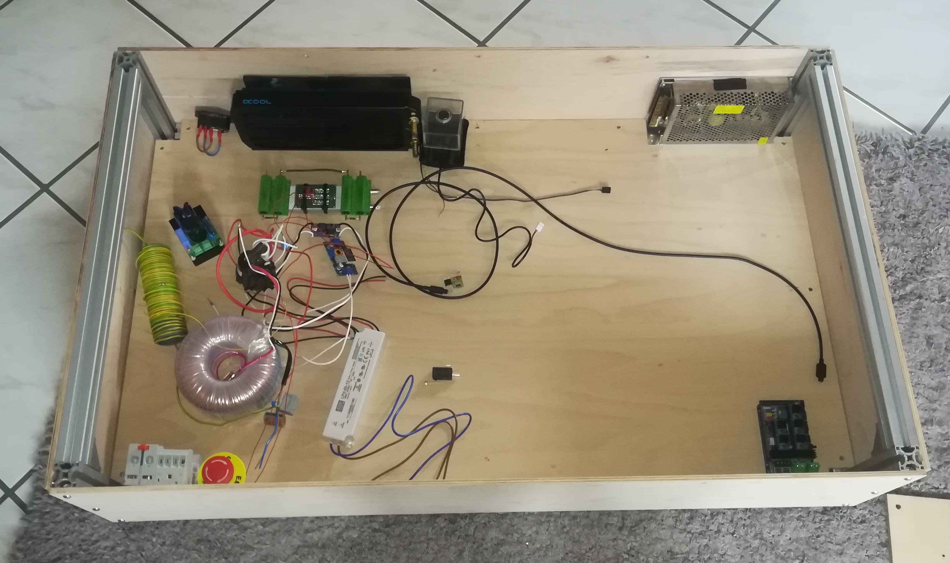
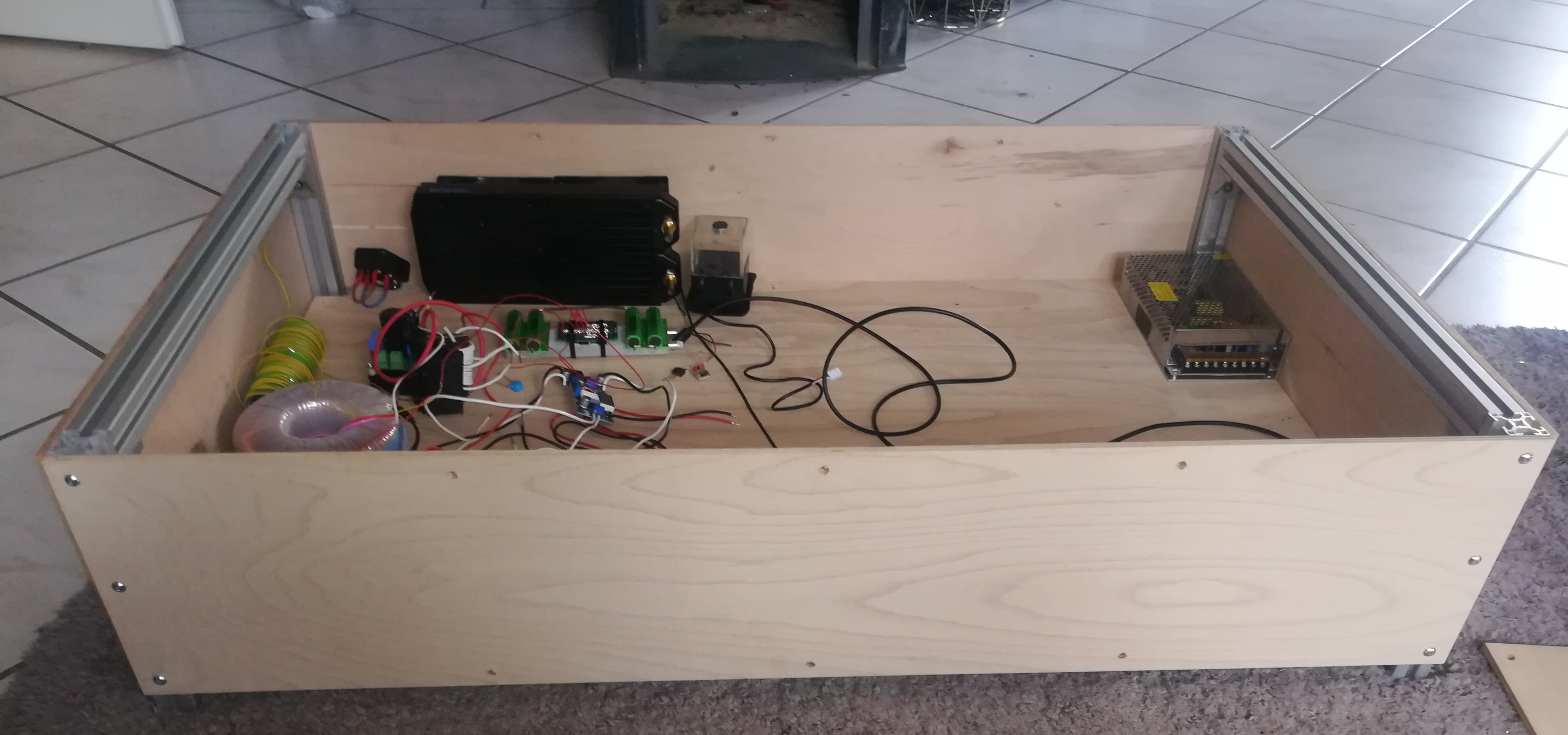
I will try to find a good place for all parts and complete the test stand in the next days.
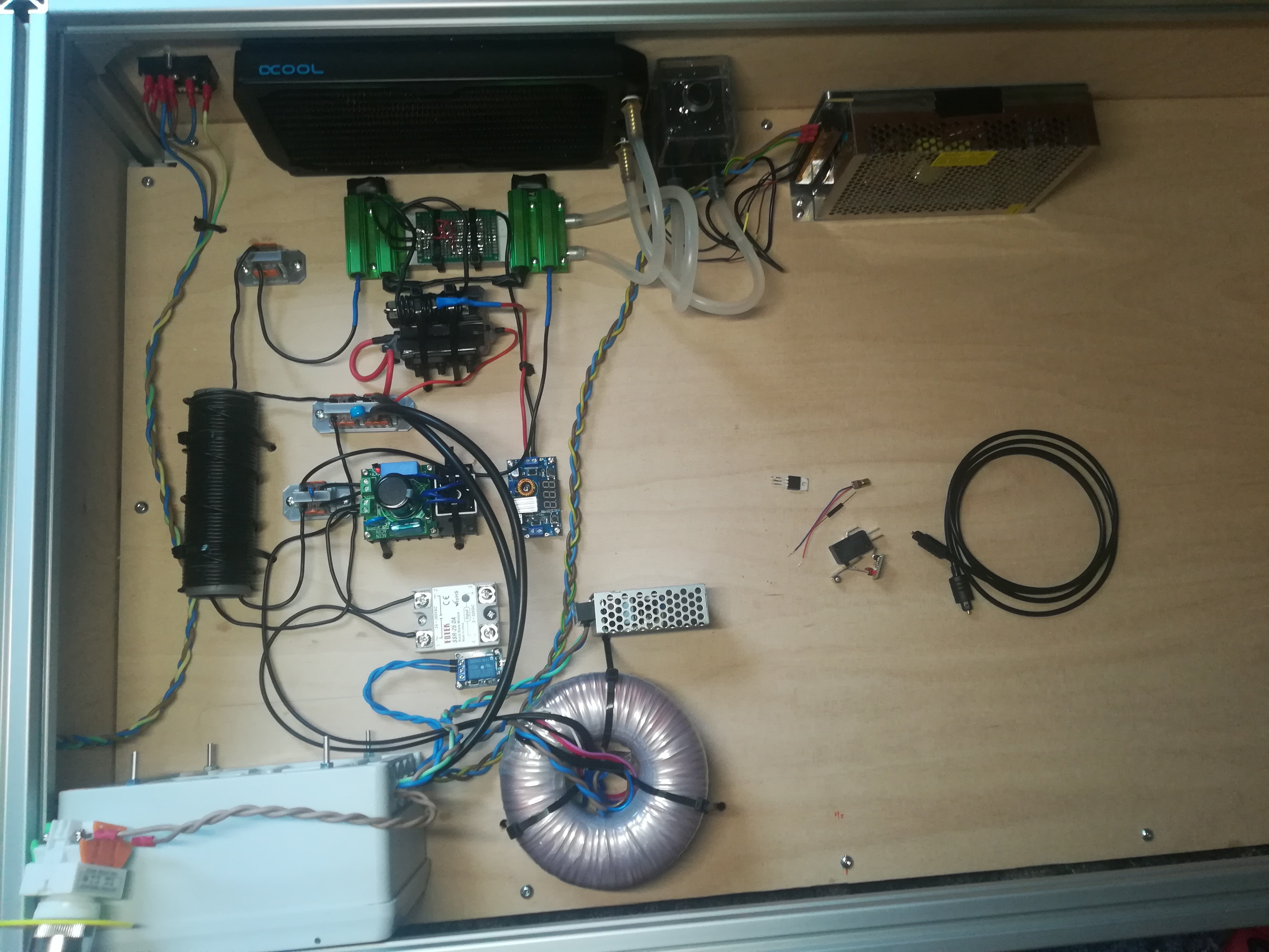
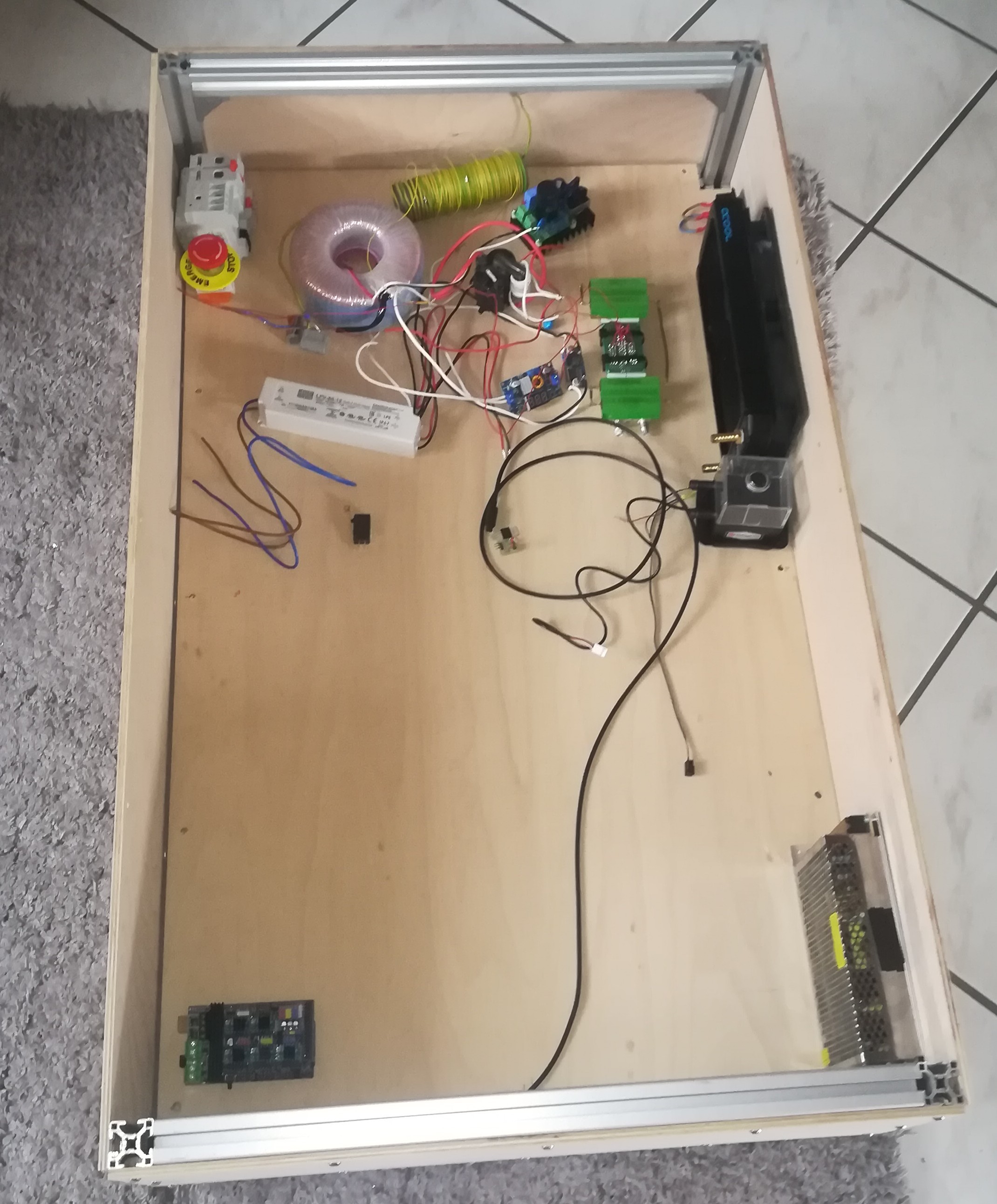
I wired the welding circuit, what's left is the trigger circuit and the printer controller.
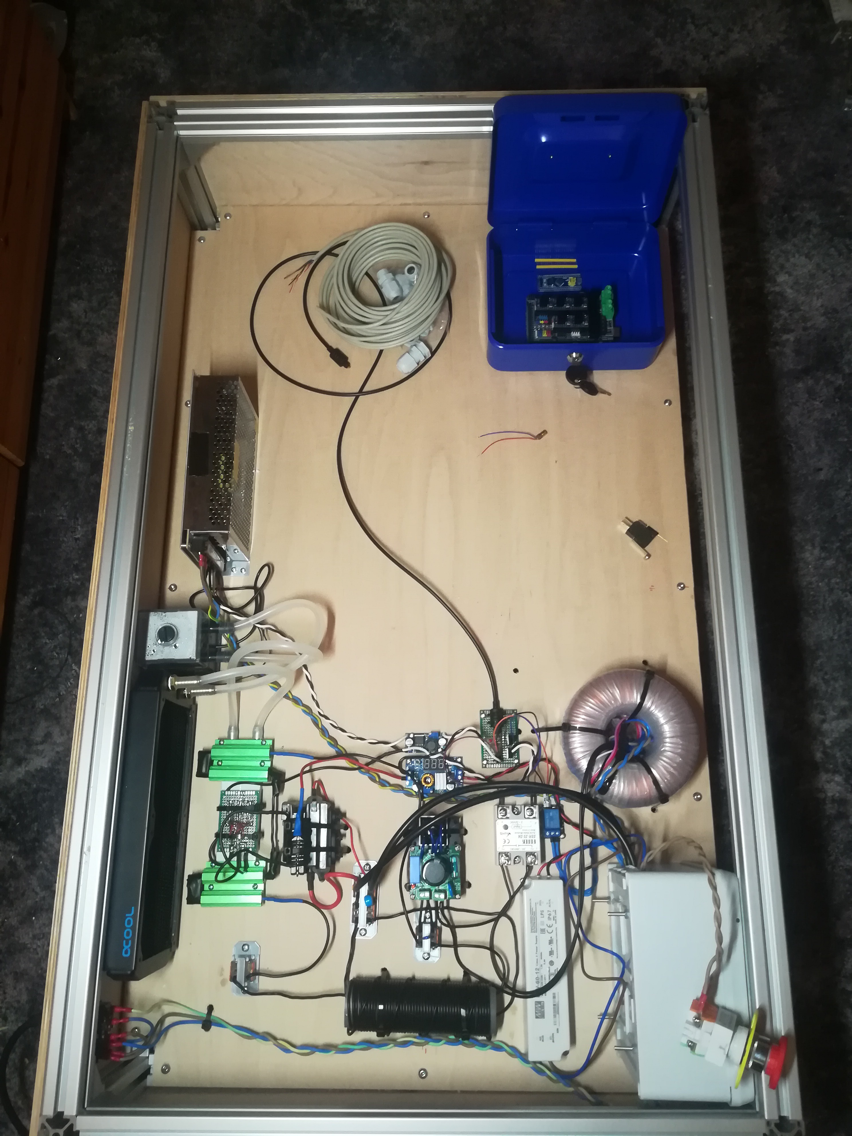
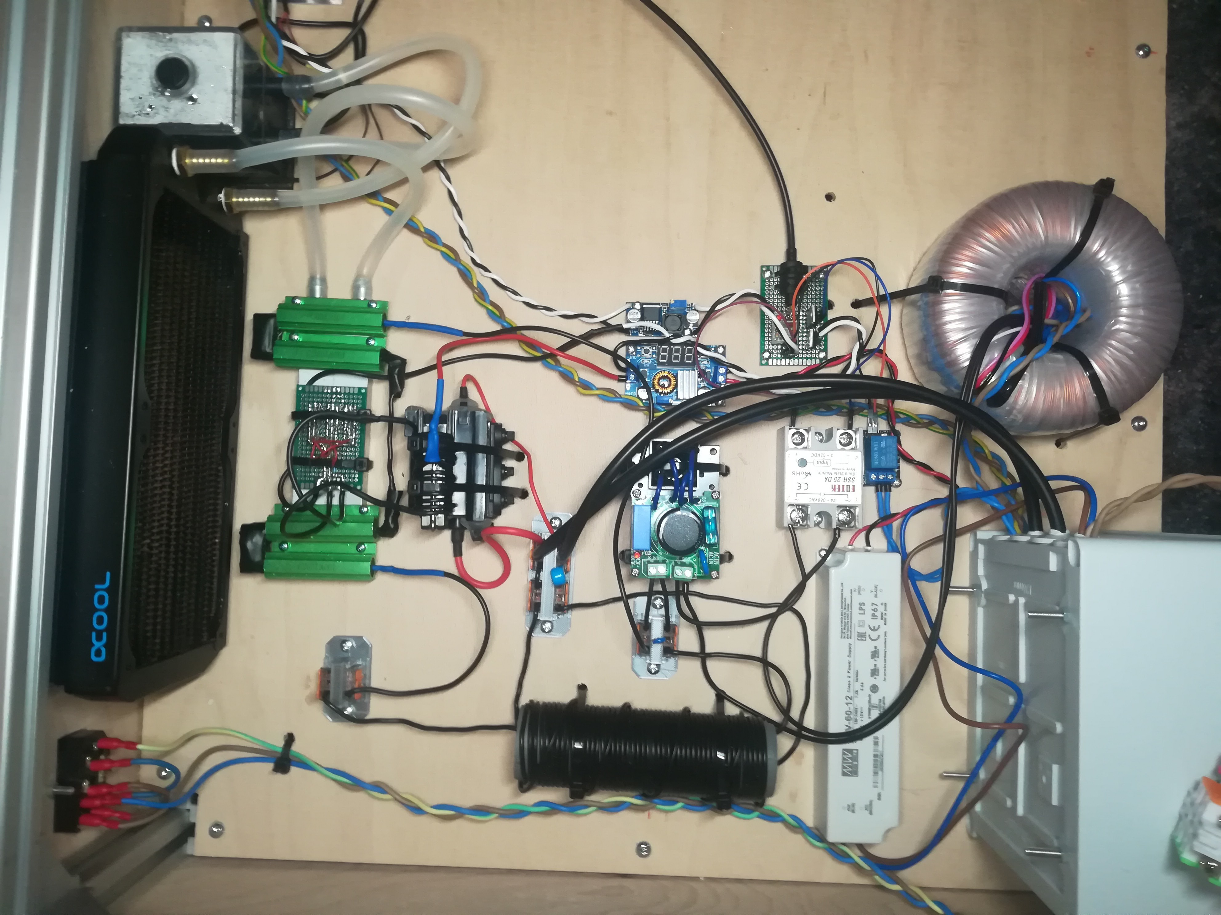
Only the printer controller left...
Discussions
Become a Hackaday.io Member
Create an account to leave a comment. Already have an account? Log In.