 Dominik Meffert
I spent the weekend testing stuff to destruction - not intended but I figured some things out.
- I tested a DC SSR which either never worked or failed at the very beginning.
- An AC SSR before the rectifier seems to work for now.
- The four 100W 100ohm resistors seem to get too hot (even with the active cooling) for continuous operation, so I maybe will try something different for current limiting, like an inverter circuit or a saturable reactor.
But the part I want to get right first is the HF Start Circuit.
Initially I had planed to pulse the HF Start and Work Current together to keep the temperature on the powder not higher than needed and to put less stress on the electronics.
But while testing this I figured out that the arc ignited not every time and the HF HV ignition arc got weaker over time until at some point the HF Starter stopped working completely.
After that I spent some time building an arc detecting circuit which could detect whether the arc has ignited and turn on the HF Start if it would extinguish. (Which I will likely never use).
I stopped working for a day because I had the false assumption that the Flyback transformer was the part that had failed and I ordered a new one and some parts to build a different flyback driver, until I tried building a new simple single mosfet driver (IRFZ44N + 470ohm resistor on the gate + 6+6 turns flyback/primary coil) for testing the transformer and... the transformer still worked. So the driver must have failed which I think was caused by turnung it on and off at a high frequency. I tested the same driver (6 IRFZ44N in parallel) with the transformer for half an hour and it did not fail, so I think the problem was not caused by mosfet overheating, but by the high frequency on and off switching.
With the driver I built yesterday I tested out the HF Starter again and the HF HV iginition arc got still weaker over time until even the spark gap stopped working. I disconnected the transformer from the circuit and it still worked and so it could only be the capacitor which must have had failed and this was the case. After replacing the capacitor with a new one it worked again, but after a short time the arc got weaker again until the capacitor failed again.
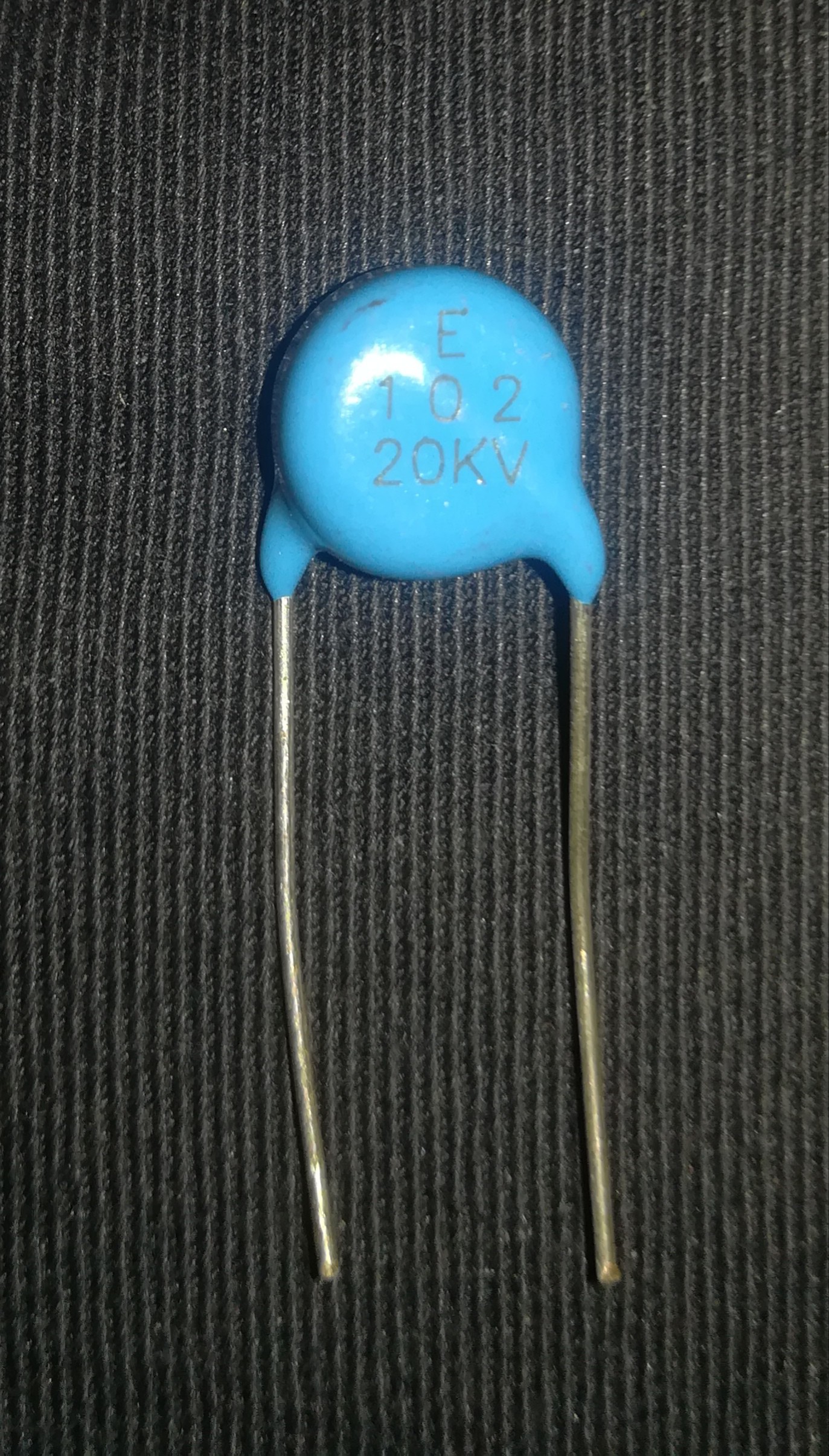
I think what happened was the capacitor (a 20kV 1nF Ceramic one) failed over time due to the high frequency of loading and unloading through the spark gap.
So I ordered 10 pieces WIMA FKP1 15nF 1600V DC capacitors which I'm planning to connect in series to increase the rating to 16000V DC 1.5nF. I read in a tesla coil forum that they are better for the high frequency and I hope they will not fail like the ceramic ones.
I think if I can get the hf hv ignition arc to work continuously I can just pulse the work current whit the SSR and everything (maybe) will be fine. Until the next problem appears :)
I figured out the reason for the death of many ceramic capacitor beside that they are not suited for HF. It was the spark gap. For some dumb reason I set it 3 times as wide as planned what leaded to the premature dead of the capacitor after under 2 minutes.
I set it to 2mm what I think should give me around 6000V and with a fresh capacitor it is enough for a 5mm spark at the tungsten electrode. I will test out how long the ceramic capacitor will last until it gets destoyed (they are not expensive).
The capacitor (still the ceramic one) lasted over an hour and would likely continue working for a long time without failing completely, but it was clearly visible on the arc that it was no longer working at "full power". I think/hope the WIMA capacitor will perform even better, but an hour is not bad and enough for testing some things out.
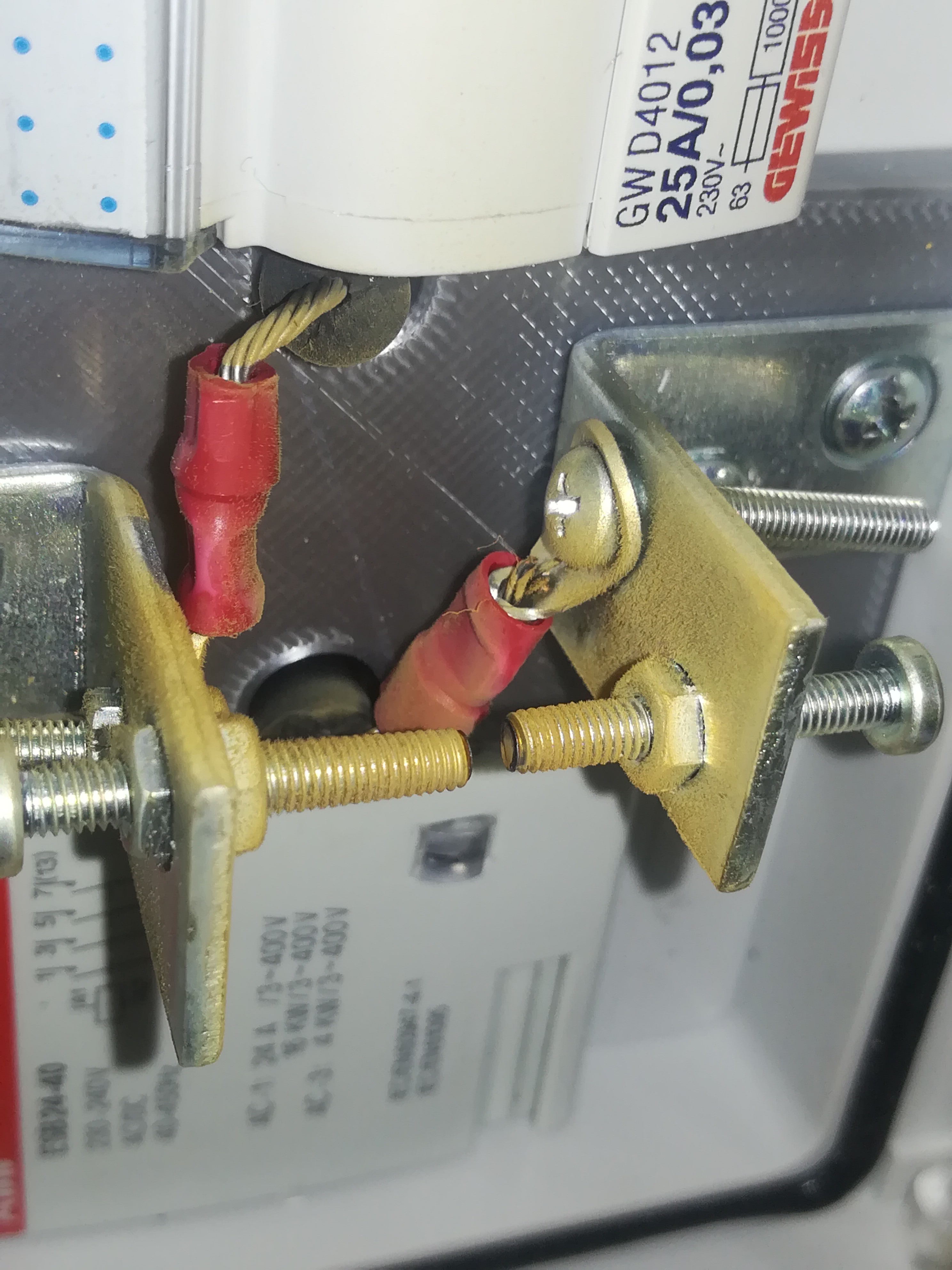
After letting it run for about 1.5 hours the spark gap was covered in an unknown (by me) yellow dust.... maybe it could be vaporised metal from the screws.
Does anyone know what that dust is?
After turning the machine off for a moment and on again, the arc was back at normal power. So maybe the capacitor was not so heavily damaged like I thought or even not at all.
Discussions
Become a Hackaday.io Member
Create an account to leave a comment. Already have an account? Log In.
The yellow dust you mentioned looks like zinc from the galvanized bolts and such. If it gets vaporized (which is probably how it got where it is), the vapor will make you sick. https://en.wikipedia.org/wiki/Zinc_shakes
Are you sure? yes | no
Ok, that's good to know. Do you think it would be better to use brass or copper bolts or will I need something made of tungsten? The spark gap is placed in an almost air tight circuit breaker box.
Are you sure? yes | no
The commercial machines use tungsten. I think copper would probably melt too quickly and brass has zinc and other stuff in it and would be worse.
I think the Miller machines have tungsten tips (maybe 4mm diameter) on copper bodies, but it has been a long time since I have had to adjust one.
Are you sure? yes | no
Ok, then I will look for something made of tungsten.
Are you sure? yes | no