 Ted Yapo
This is more notes to myself than anything else because this is the only place I seem to be able to find my notes.
Everything is happening in the build logs on this one.
experiments with fast start-up oscillators
Already have an account? Log in.
To make the experience fit your profile, pick a username and tell us what interests you.
This is more notes to myself than anything else because this is the only place I seem to be able to find my notes.
Everything is happening in the build logs on this one.
I was thinking about ring oscillators -- you know the ones -- three or more (an odd number) inverters connected in a ring becomes an oscillator. Then I thought about the fact that most CMOS logic families these days are buffered -- there's actually three inverting stages inside each inverter. So, will they oscillate if you just hook the output back to the input? I'm guessing they will, but that's perhaps not too interesting.
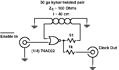
What if, instead, we used a 2-input inverting gate as an oscillator -- either NOR or NAND will do -- feeding back the output to one of the inputs, and using the second input as an oscillator enable? And, instead of relying simply on the propagation delay to set the oscillation frequency, why not introduce a section of transmission line to provide a fixed delay and stabilize things a bit?
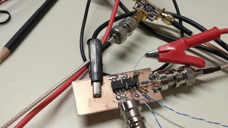
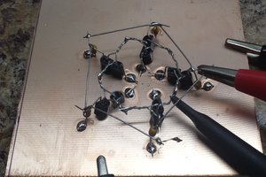
Here's a schematic of a quick prototype whipped up at the bench to test things. The 1k output resistor works as a 21:1 probe when combined with a scope's 50-ohm input. The 91 ohm resistor roughly matches the characteristic impedance of a twisted pair of 30 ga kynar-covered wire-wrap wire -- accounting for the approximately 12-Ohm output impedance of the gate. I have some 86.6-Ohm ones I like to use for this, but couldn't find them immediately.
The enable input is inverted: when the enable goes low, the gate behaves like an inverter, and oscillation commences immediately.
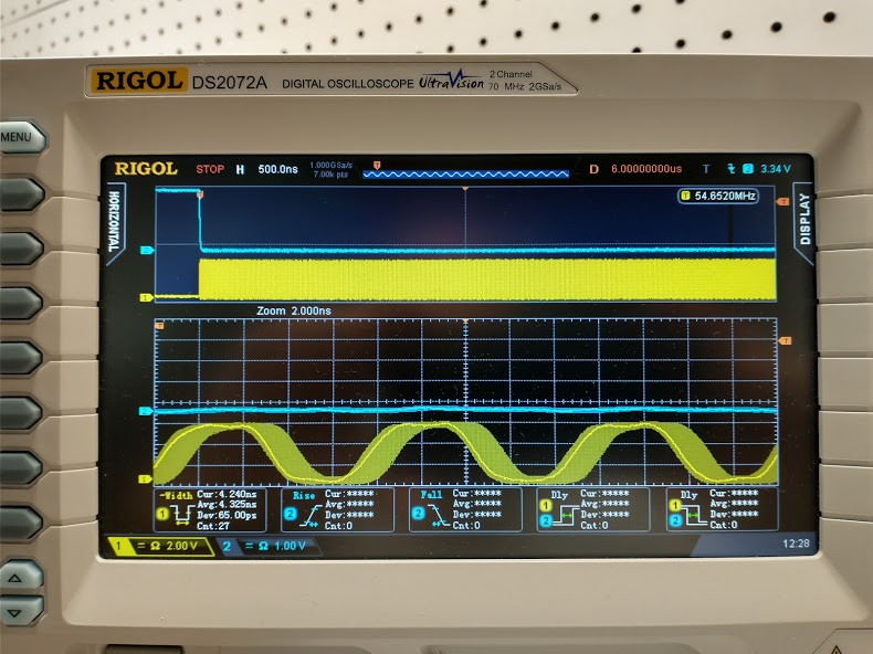
How well does it work? Here's some sample output. The cyan trace is the enable line; when enable goes low, the oscillation starts, as displayed on the yellow trace. The zoomed section below shows a portion of the output 6 us after the enable goes low. At the 54.65 MHz oscillation frequency, this is approximately 328 cycles later. The peak jitter here seems to be around 2ns. This 2 ns in 6 us is very roughly a stability of 0.033%, which doesn't seem too bad for what we're working with here.
This oscillator *is* very sensitive to external influences, however. Merely bringing your hand within a foot or so of the twisted pair will shift the waveforms noticeably. Touching the 74AC02 with a finger will slow the oscillator down, then you can watch it creep back up to speed as the IC cools again.
It's very sensitive to supply voltage, too, which will be quite convenient for tuning and further stabilization.
Kynar is also very piezoelectric, so and introduce electrical noise from vibration.
Why do I care? The Tektronix 11801 oscilloscope uses a gated ring oscillator as part of its timebase. I'd like to re-create something like this. While Tek used a custom IC to perform this function, I am forced to wonder if something similar can be made with off-the shelf parts.
The fact that you can tune the frequency with the supply voltage -- this fact is used in many ICs to turn a ring oscillator into a VCO -- is interesting. I'd like to get a faster, modern dual gate -- say a 74LVC2G02 or 74AUC2G02 (or their NAND equivalents) -- and run one gate as the oscillator in a PLL. Synchronized to a high-stability crystal oscillator, this should allow me to stabilize the other gate on the same die as well, eliminating variations in propagation delay due to supply voltage and temperature.
Meanwhile, using a longer delay line relative to a faster gate will reduce the influence of propagation delay variation. Using identical PCB-trace delay lines on the PLL and gated oscillator sections should allow the PLL to stabilize the system for variations in the line delay, too.
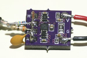
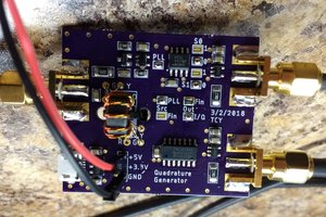
I have a PCB I've been trying to send out for some time now that implements a version of this PLL-stabilization scheme. It's time to finally send that thing off.
One issue with all of this is that the Tek scheme appears to have used an ECL circuit for the oscillator. This probably benefits from the differential signaling, which should reduce noise and subsequent jitter in the output.
Unless I can find a suitable dual -gate ECL part to turn into an oscillator, I may be forced...
Read more »

I think kynar is the most piezoelectric known polymer -- it was at one time, anyway. It's used in vibration-sensing cables, like the ones run under security perimeters to detect vehicles driving over.
This obviously isn't the ideal situation, but one 74AC gate will drive 100-ohm line, while you really need to parallel two gates to drive a 50-ohm line at 5V. It was also quicker to prototype this way :-)
The final implementation will use stripline on a PCB for the feedback delay line.

That's pretty neat. How do you know the characteristic impedance of that twisted pair? Is that just a look-up in a table or something? Does the TPI impact the impedance? Of is it just a function of the insulation characteristics and the conductor spacing?
there's an old EDN design idea about making this stuff. They quote 10 turns/cm, tell you how to count them, and measure 102 ohms with TDR.
https://www.edn.com/tiny-twisted-pair-transmission-line-solves-test-fixture-woes/
there are calculators, too, but they seem to be based on some "simplifying assumptions"
https://www.allaboutcircuits.com/tools/twisted-pair-impedance-calculator/
when plug in the data for Allied's wire-wrap wire (https://www.awcwire.com/part.aspx?partname=kyn30-1), for instance, I get 19.5 Ohms. Oops. This may be because of kynar's high dielectric constant. I am guessing that the models all assume the dielectric between the wires fills space, when in reality it's just 4 mils thick or Er = 8.4, then air with Er of 1.
Also, who knows what they did to model the twisting -- notably, the rate of which they don't ask. As a point of comparison, using a parallel-line model, like this calculator:
https://www.mantaro.com/resources/impedance-calculator.htm
gives you 49.4 Ohms. Better, but not the hundred-odd we observe, either.
In all these calculators I used:
wire dia: 10 mils
insulation thickness: 4 mils
Er: 8.4

I wonder how many engineers still use that "good advice" ;-) I used to twist standard 0.25mm PVC isolated TP cable for an "120R" CAN network (in fact, the stand SAE J1939 CAN cable is 20 AWG TP and it's assumed to be Er = 120 but who knows how many parameter have to be controlled).
@Thomas the truth is, for most applications close is good enough

I am not sure, if Kynar is really piezoelectric. But for sure it has some elastic properties and any vibration leads to tiny fluctuations of the distance of the conductors to each other and to the environment. That changes the capacity and that the properties of this transmission line. A good coax would at least reduce the effects of the hand. Generally such a behavior is called microphony.