 Ted Yapo
I was thinking about ring oscillators -- you know the ones -- three or more (an odd number) inverters connected in a ring becomes an oscillator. Then I thought about the fact that most CMOS logic families these days are buffered -- there's actually three inverting stages inside each inverter. So, will they oscillate if you just hook the output back to the input? I'm guessing they will, but that's perhaps not too interesting.
What if, instead, we used a 2-input inverting gate as an oscillator -- either NOR or NAND will do -- feeding back the output to one of the inputs, and using the second input as an oscillator enable? And, instead of relying simply on the propagation delay to set the oscillation frequency, why not introduce a section of transmission line to provide a fixed delay and stabilize things a bit?
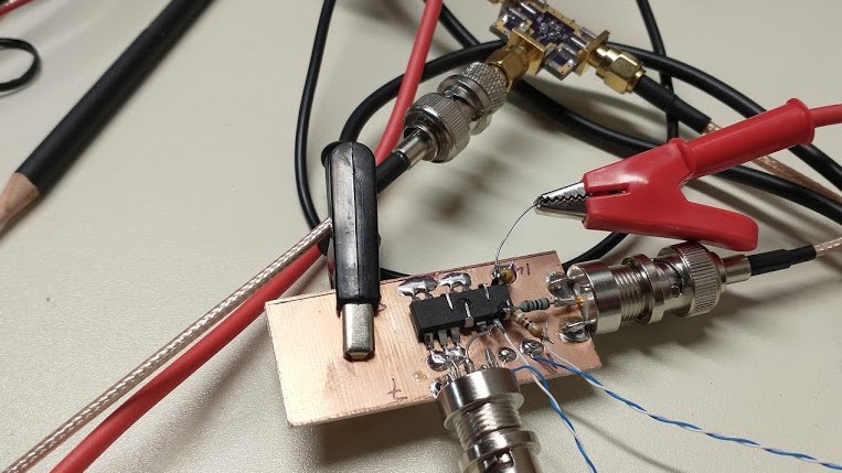
Here's a schematic of a quick prototype whipped up at the bench to test things. The 1k output resistor works as a 21:1 probe when combined with a scope's 50-ohm input. The 91 ohm resistor roughly matches the characteristic impedance of a twisted pair of 30 ga kynar-covered wire-wrap wire -- accounting for the approximately 12-Ohm output impedance of the gate. I have some 86.6-Ohm ones I like to use for this, but couldn't find them immediately.
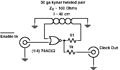
The enable input is inverted: when the enable goes low, the gate behaves like an inverter, and oscillation commences immediately.
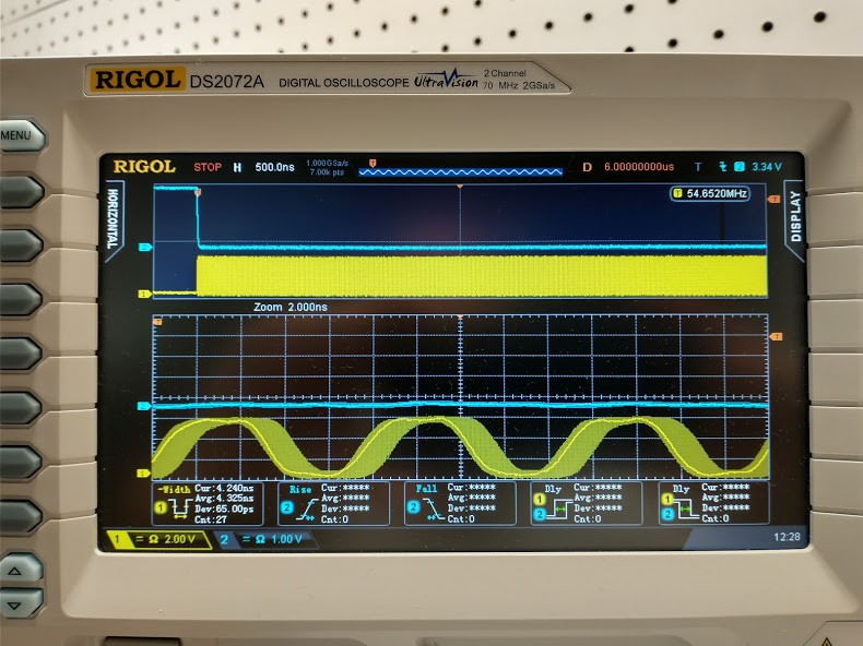
How well does it work? Here's some sample output. The cyan trace is the enable line; when enable goes low, the oscillation starts, as displayed on the yellow trace. The zoomed section below shows a portion of the output 6 us after the enable goes low. At the 54.65 MHz oscillation frequency, this is approximately 328 cycles later. The peak jitter here seems to be around 2ns. This 2 ns in 6 us is very roughly a stability of 0.033%, which doesn't seem too bad for what we're working with here.
This oscillator *is* very sensitive to external influences, however. Merely bringing your hand within a foot or so of the twisted pair will shift the waveforms noticeably. Touching the 74AC02 with a finger will slow the oscillator down, then you can watch it creep back up to speed as the IC cools again.
It's very sensitive to supply voltage, too, which will be quite convenient for tuning and further stabilization.
Kynar is also very piezoelectric, so and introduce electrical noise from vibration.
Why?
Why do I care? The Tektronix 11801 oscilloscope uses a gated ring oscillator as part of its timebase. I'd like to re-create something like this. While Tek used a custom IC to perform this function, I am forced to wonder if something similar can be made with off-the shelf parts.
Next Steps
The fact that you can tune the frequency with the supply voltage -- this fact is used in many ICs to turn a ring oscillator into a VCO -- is interesting. I'd like to get a faster, modern dual gate -- say a 74LVC2G02 or 74AUC2G02 (or their NAND equivalents) -- and run one gate as the oscillator in a PLL. Synchronized to a high-stability crystal oscillator, this should allow me to stabilize the other gate on the same die as well, eliminating variations in propagation delay due to supply voltage and temperature.
Meanwhile, using a longer delay line relative to a faster gate will reduce the influence of propagation delay variation. Using identical PCB-trace delay lines on the PLL and gated oscillator sections should allow the PLL to stabilize the system for variations in the line delay, too.
I have a PCB I've been trying to send out for some time now that implements a version of this PLL-stabilization scheme. It's time to finally send that thing off.
One issue with all of this is that the Tek scheme appears to have used an ECL circuit for the oscillator. This probably benefits from the differential signaling, which should reduce noise and subsequent jitter in the output.
Unless I can find a suitable dual -gate ECL part to turn into an oscillator, I may be forced to very carefully impedance match the delay line to avoid reflections which can nudge the signal past the switching threshold at the wrong time and lead to jitter. There's also the issue of the PLL causing noise in the supply voltage which could result in additional jitter -- and perhaps even worse, mode-locking with the PLL. It might be possible to turn off the PLL briefly while the timebase is triggered, eliminating this influence. Experiments will tell.
Discussions
Become a Hackaday.io Member
Create an account to leave a comment. Already have an account? Log In.
To stabilize oscillations, your feedback path must suppress all frequencies but the one you desire having fixed delay feedback doesn't lock the frequency, because you have expression for round trip delay where uncontrolled gate delay is added to presumably fixed (if perfectly shielded and mechanically dead) transmission line delay. That's why most oscillators are built around some dampened resonator, and active element just does a little bit of regeneration to recuperate the energy loss in resonator (and tapped off output).
In this case, you would experiment with transmission lines creating standing waves at wanted frequencies, and making your circuit dependent on achieving that resonance to have the sufficient signal level at gate input.
Edit: Oh, I didn't read carefully; You actually want your oscillator to be sensitive and tuned.
Are you sure? yes | no
yeah, in this case, I can't afford the long startup time you get with a high-Q tuned circuit typically used for precision oscillators. It has to start right up, ideally with very little jitter in the startup time, then a very stable oscillation.
I figure if I can use a gate with very low jitter, the thing might end up stable. For instance, if I take a clock distribution buffer with say 200 fs RMS additive jitter, after 100 cycles, it should have only around 2 ps RMS jitter.
oh, and yeah, I want to use another gate on the same die to adjust the supply voltage to servo the gate delay and keep it stable
Are you sure? yes | no